LOWER INSTRUMENT PANEL REMOVAL
CAUTION / NOTICE / HINT
Tech Tips
-
Use the same procedure for RHD and LHD vehicles.
-
The procedure listed below is for LHD vehicles.
CAUTION:
w/ Airbag System:
Some of these service operations affect the SRS airbag system. Read the precautionary notices concerning the SRS airbag system before servicing.
PROCEDURE
-
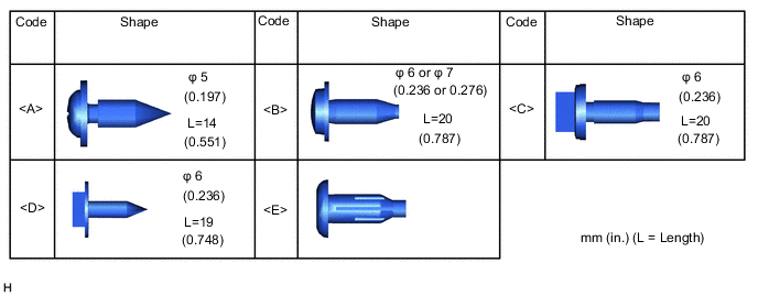
TABLE OF BOLT, SCREW, NUT AND CLIP
Tech Tips
All bolts, screws and clips relevant to installing and removing the instrument panel are shown along with their alphabetic code in the table below.
-
PRECAUTION (w/ Airbag System)
Note
After turning the ignition switch off, waiting time may be required before disconnecting the cable from the battery terminal. Therefore, make sure to read the disconnecting the cable from the battery terminal notice before proceeding with work.
-
DISCONNECT CABLE FROM NEGATIVE BATTERY TERMINAL (w/ Airbag System)
CAUTION:
Wait at least 90 seconds after disconnecting the cable from the negative (-) battery terminal to disable the SRS system.
Note
When disconnecting the cable, some systems need to be initialized after the cable is reconnected.
-
REMOVE UPPER INSTRUMENT PANEL SUB-ASSEMBLY
-
REMOVE CONSOLE BOX ASSEMBLY (w/ Console Box Lid)
-
REMOVE REAR CONSOLE BOX SUB-ASSEMBLY (w/ Rear Console Box)
-
REMOVE FRONT CONSOLE BOX (w/o Console Box Lid)
-
REMOVE HEADLIGHT DIMMER SWITCH ASSEMBLY
-
REMOVE CONTROL KNOB SUB-ASSEMBLY (for Manual Cooler System, for Manual Air Conditioning System)
-
REMOVE INTEGRATION PANEL SUB-ASSEMBLY (for Manual Cooler System, for Manual Air Conditioning System)
-
REMOVE AIR CONDITIONING CONTROL ASSEMBLY (for Automatic Air Conditioning System)
-
REMOVE CENTER INSTRUMENT CLUSTER FINISH PANEL ASSEMBLY
-
w/o Audio:
-
Remove the 4 screws.
-

Place Hands Here 
Remove in this Direction Place your hands at the position shown in the illustration and pull as shown to detach the clip and guide.
-
Disconnect the connector and remove the center instrument cluster finish panel assembly.
-
-
w/ Audio, for Radio Receiver Type:
-
Remove the 4 screws.
-

Place Hands Here Remove in this Direction Place your hands at the position shown in the illustration and pull as shown to detach the clip and guide.
-
Disconnect the connector and remove the center instrument cluster finish panel assembly.
-
-
w/ Audio, for Radio and Display Type:
-

Remove the 4 screws.
-
Place Hands Here Remove in this Direction Place your hands at the position shown in the illustration and pull as shown to detach the clip and guide.
-
Disconnect the connector and remove the center instrument cluster finish panel assembly.
-
-
w/ Audio, for Navigation Receiver Type:
-
Remove the 4 screws.
-
Place Hands Here Remove in this Direction Place your hands at the position shown in the illustration and pull as shown to detach the clip and guide.
-
Disconnect the connector and remove the center instrument cluster finish panel assembly.
-
-
-
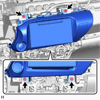
REMOVE NO. 1 INSTRUMENT PANEL UNDER COVER SUB-ASSEMBLY (w/ Knee Airbag)
-
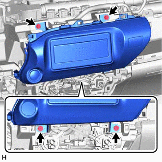
*a Screw <A> Remove the 2 screws <A>.
-
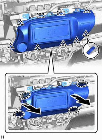
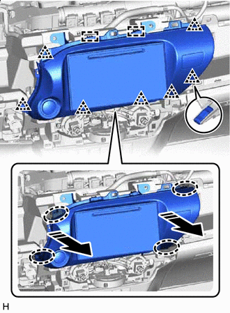
Place Hands Here Remove in this Direction Place your hands at the position shown in the illustration and pull as shown to detach the clip, claw and guide.
-
Detach the claw and disconnect the DLC3 and remove the No. 1 instrument panel under cover sub-assembly.
-
-
REMOVE LOWER NO. 1 INSTRUMENT PANEL AIRBAG ASSEMBLY (w/ Knee Airbag)
-
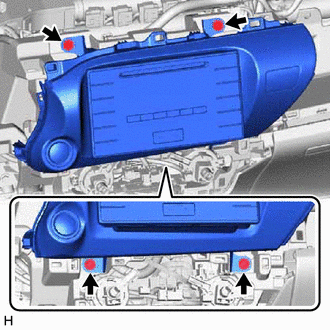
REMOVE LOWER INSTRUMENT PANEL FINISH PANEL SUB-ASSEMBLY (w/o Knee Airbag)
-
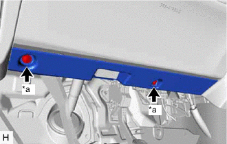
*a Protective Tape *b Screw <A> Put protective tape around the lower instrument panel finish panel sub-assembly.
-
Remove the 2 screws <A>.
-
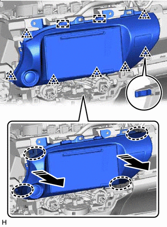
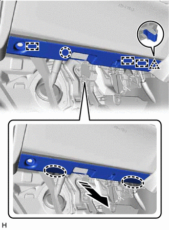
Place Hands Here Remove in this Direction Place your hands at the position shown in the illustration and pull as shown to detach the clip and claw.
-
Detach the claw and disconnect the DLC3 and remove the lower instrument panel finish panel sub-assembly.
-
-
REMOVE NO. 2 INSTRUMENT PANEL UNDER COVER SUB-ASSEMBLY
-
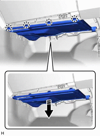
Remove in this Direction Detach the claw and pull as shown in the illustration.
-
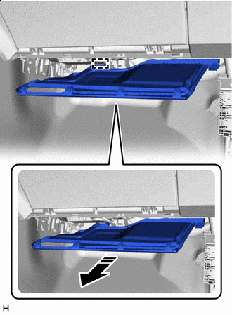
Remove in this Direction Pull as shown in the illustration, detach the guide and remove the No. 2 instrument panel under cover sub-assembly.
-
-
REMOVE GLOVE COMPARTMENT DOOR ASSEMBLY
-
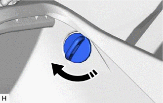
Remove in this Direction Twist the glove door stopper pin as shown in the illustration and remove it.
Tech Tips
Use the same procedure for both glove door stopper pins.
-
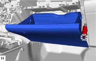
Open the glove compartment door assembly, detach the claw and disconnect the glove compartment door stopper sub-assembly.
Tech Tips
Pull diagonally to remove the glove compartment door stopper sub-assembly.
-
Remove in this Direction Pull as shown in the illustration to detach the hinge and remove the glove compartment door assembly.
-
-
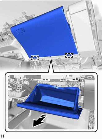
REMOVE LOWER INSTRUMENT COVER SUB-ASSEMBLY
-
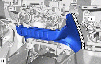
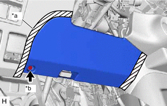
*a Protective Tape Put protective tape around the lower instrument cover sub-assembly.
-
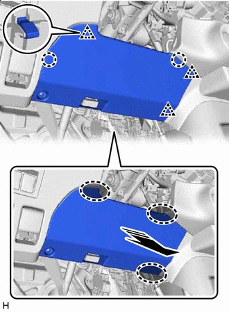
Place Hands Here Remove in this Direction Place your hands at the position shown in the illustration and pull as shown to detach the clip and claw.
-
Disconnect the connector and remove the lower instrument cover sub-assembly.
-
-
REMOVE GLOVE COMPARTMENT DOOR STOPPER SUB-ASSEMBLY
-
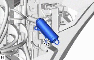
Detach the claw and remove the glove compartment door stopper sub-assembly.
-
-
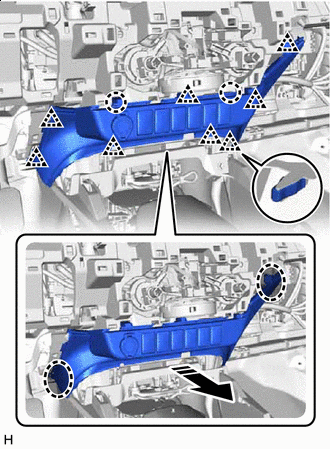
REMOVE LOWER INSTRUMENT PANEL SUB-ASSEMBLY
-
Remove the 7 screws <B>, 2 bolts <C> and screw <D>.
-
Detach the guide and disconnect the connector.
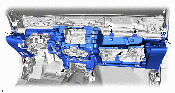
*a Screw <B> *b Bolt <C> *c Screw <D> *d Guide -
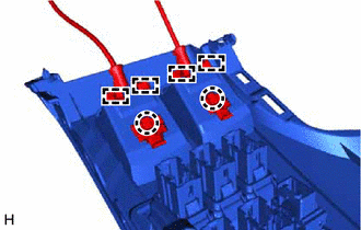
Detach the claw and guide to disconnect the hood lock control lever sub-assembly and fuel lid lock open lever.
-
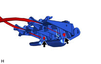
Disconnect the hood lock control cable and fuel lid lock open cable and remove the lower instrument panel sub-assembly.
-