REAR VIEW MONITOR SYSTEM Reverse Signal Circuit
| DTC Code | DTC Name |
|---|---|
| Reverse Signal Circuit |
DESCRIPTION
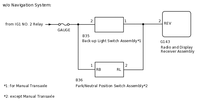
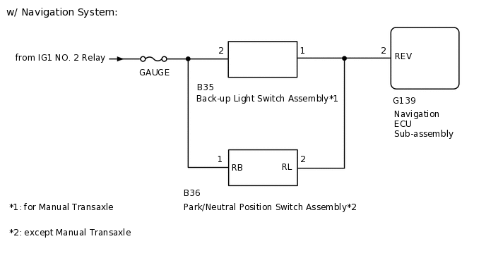
The radio and display receiver assembly*1 or navigation ECU sub-assembly*2 receives a reverse signal from the park/neutral position switch assembly*3 or back-up light switch assembly*4.
*1: w/o Navigation System
*2: w/ Navigation System
*3: except Manual Transaxle
*4: for Manual Transaxle
WIRING DIAGRAM
CAUTION / NOTICE / HINT
Inspect the fuses for circuits related to this system before performing the following inspection procedure.
PROCEDURE
CHECK VEHICLE SIGNAL (DISPLAY CHECK MODE)
-
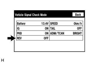
Enter the "Function Check/Setting I" mode and select "Vehicle Signal".
Check that the display changes between ON and OFF according to the shift lever position.
OK
Shift Lever Position
Display
R
ON
Except R
OFF
Tip:This display is updated once per second. As a result, it is normal for the display to lag behind the actual shift lever position.
Result
Proceed to
OK
NG (w/o Navigation System)
NG (w/ Navigation System)
NG (w/ Navigation System) CHECK NAVIGATION ECU SUB-ASSEMBLYClick here
-
CHECK RADIO AND DISPLAY RECEIVER ASSEMBLY
-
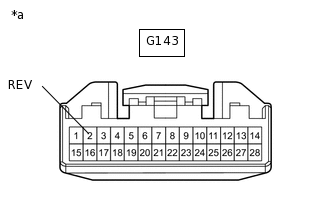
*a
Front view of wire harness connector
(to Radio and Display Receiver Assembly)
Disconnect the radio and display receiver assembly connector.
Measure the voltage according to the value(s) in the table below.
Standard Voltage
Tester Connection
Condition
Specified Condition
G143-2 (REV) - Body ground
Ignition switch ON, shift lever in R
11 to 14 V
G143-2 (REV) - Body ground
Ignition switch ON, shift lever not in R
Below 1 V
Result
Proceed to
OK
NG (except Manual Transaxle)
NG (for Manual Transaxle)
NG (except Manual Transaxle) CHECK HARNESS AND CONNECTOR (RADIO AND DISPLAY RECEIVER ASSEMBLY - PARK/NEUTRAL POSITION SWITCH ASSEMBLY)Click here
NG (for Manual Transaxle) CHECK HARNESS AND CONNECTOR (RADIO AND DISPLAY RECEIVER ASSEMBLY - BACK-UP LIGHT SWITCH ASSEMBLY)Click here
-
CHECK NAVIGATION ECU SUB-ASSEMBLY
-
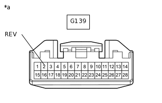
*a
Front view of wire harness connector
(to Navigation ECU Sub-assembly)
Disconnect the navigation ECU sub-assembly connector.
Measure the voltage according to the value(s) in the table below.
Standard Voltage
Tester Connection
Condition
Specified Condition
G139-2 (REV) - Body ground
Ignition switch ON, shift lever in R
11 to 14 V
G139-2 (REV) - Body ground
Ignition switch ON, shift lever not R
Below 1 V
Result
Proceed to
OK
NG (except Manual Transaxle)
NG (for Manual Transaxle)
NG (except Manual Transaxle) CHECK HARNESS AND CONNECTOR (NAVIGATION ECU SUB-ASSEMBLY - PARK/NEUTRAL POSITION SWITCH ASSEMBLY)Click here
NG (for Manual Transaxle) CHECK HARNESS AND CONNECTOR (NAVIGATION ECU SUB-ASSEMBLY - BACK-UP LIGHT SWITCH ASSEMBLY)Click here
-
CHECK HARNESS AND CONNECTOR (RADIO AND DISPLAY RECEIVER ASSEMBLY - PARK/NEUTRAL POSITION SWITCH ASSEMBLY)
Disconnect the G143 radio and display receiver assembly connector.
Disconnect the B36 park/neutral position switch assembly connector.
Measure the resistance according to the value(s) in the table below.
Standard Resistance
Tester Connection
Condition
Specified Condition
G143-2 (REV) - B36-2 (RL)
Always
Below 1 Ω
G143-2 (REV) - Body ground
Always
10 kΩ or higher
Result
Proceed to
OK
NG
NG REPAIR OR REPLACE HARNESS OR CONNECTOR
CHECK HARNESS AND CONNECTOR (PARK/NEUTRAL POSITION SWITCH ASSEMBLY - BATTERY)
-
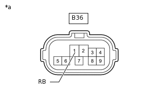
*a
Front view of wire harness connector
(to Park/Neutral Position Switch Assembly)
Disconnect the park/neutral position switch assembly connector.
Measure the voltage according to the value(s) in the table below.
Standard Voltage
Tester Connection
Switch Condition
Specified Condition
B36-1 (RB) - Body ground
Ignition switch ON
11 to 14 V
Result
Proceed to
OK (for U660F)
OK (for U760E)
OK (for U760F)
OK (for K111)
OK (for K111F)
NG
NG REPAIR OR REPLACE HARNESS OR CONNECTOR
-
CHECK HARNESS AND CONNECTOR (NAVIGATION ECU SUB-ASSEMBLY - PARK/NEUTRAL POSITION SWITCH ASSEMBLY)
Disconnect the G139 navigation ECU sub-assembly connector.
Disconnect the B36 park/neutral position switch assembly connector.
Measure the resistance according to the value(s) in the table below.
Standard Resistance
Tester Connection
Condition
Specified Condition
G139-2 (REV) - B36-2 (RL)
Always
Below 1 Ω
G139-2 (REV) - Body ground
Always
10 kΩ or higher
Result
Proceed to
OK
NG
NG REPAIR OR REPLACE HARNESS OR CONNECTOR
CHECK HARNESS AND CONNECTOR (PARK/NEUTRAL POSITION SWITCH ASSEMBLY - BATTERY)
-
*a
Front view of wire harness connector
(to Park/Neutral Position Switch Assembly)
Disconnect the park/neutral position switch assembly connector.
Measure the voltage according to the value(s) in the table below.
Standard Voltage
Tester Connection
Switch Condition
Specified Condition
B36-1 (RB) - Body ground
Ignition switch ON
11 to 14 V
Result
Proceed to
OK (for U660F)
OK (for U760E)
OK (for U760F)
OK (for K111)
OK (for K111F)
NG
NG REPAIR OR REPLACE HARNESS OR CONNECTOR
-
CHECK HARNESS AND CONNECTOR (RADIO AND DISPLAY RECEIVER ASSEMBLY - BACK-UP LIGHT SWITCH ASSEMBLY)
Disconnect the G143 radio and display receiver assembly connector.
Disconnect the B35 back-up light switch assembly connector.
Measure the resistance according to the value(s) in the table below.
Standard Resistance
Tester Connection
Condition
Specified Condition
G143-2 (REV) - B35-1
Always
Below 1 Ω
G143-2 (REV) - Body ground
Always
10 kΩ or higher
Result
Proceed to
OK
NG
NG REPAIR OR REPLACE HARNESS OR CONNECTOR
CHECK HARNESS AND CONNECTOR (BACK-UP LIGHT SWITCH ASSEMBLY - BATTERY)
-

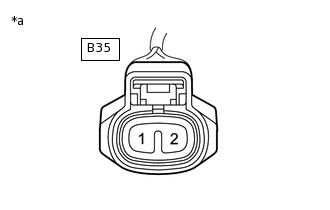
*a
Front view of wire harness connector
(to Back-up Light Switch Assembly)
Disconnect the back-up light switch assembly connector.
Measure the voltage according to the value(s) in the table below.
Standard Voltage
Tester Connection
Switch Condition
Specified Condition
B35-2 - Body ground
Ignition switch ON
11 to 14 V
Result
Proceed to
OK (for EA64)
OK (for EA64F)
OK (for EB61)
OK (for EB61F)
NG
NG REPAIR OR REPLACE HARNESS OR CONNECTOR
-
CHECK HARNESS AND CONNECTOR (NAVIGATION ECU SUB-ASSEMBLY - BACK-UP LIGHT SWITCH ASSEMBLY)
Disconnect the G139 navigation ECU sub-assembly connector.
Disconnect the B35 back-up light switch assembly connector.
Measure the resistance according to the value(s) in the table below.
Standard Resistance
Tester Connection
Condition
Specified Condition
G139-2 (REV) - B35-1
Always
Below 1 Ω
G139-2 (REV) - Body ground
Always
10 kΩ or higher
Result
Proceed to
OK
NG
NG REPAIR OR REPLACE HARNESS OR CONNECTOR
CHECK HARNESS AND CONNECTOR (BACK-UP LIGHT SWITCH ASSEMBLY - BATTERY)
-
*a
Front view of wire harness connector
(to Back-up Light Switch Assembly)
Disconnect the back-up light switch assembly connector.
Measure the voltage according to the value(s) in the table below.
Standard Voltage
Tester Connection
Switch Condition
Specified Condition
B35-2 - Body ground
Ignition switch ON
11 to 14 V
Result
Proceed to
OK (for EA64)
OK (for EA64F)
OK (for EB61F)
NG
NG REPAIR OR REPLACE HARNESS OR CONNECTOR
-