ПРОКЛАДКА ГОЛОВКИ БЛОКА ЦИЛИНДРОВ СНЯТИЕ
Note
-
When replacing the parts in the following chart (A), replace the No. 1 injection pipe sub-assembly, No. 2 injection pipe sub-assembly and/or fuel inlet pipe sub-assembly with new ones.
Replaced Parts (A) Pipes Requiring New Replacement Injector assembly (including shuffling the injector assemblies between the cylinders)
-
No. 1 injection pipe sub-assembly
-
No. 2 injection pipe sub-assembly
Supply pump assembly Fuel inlet pipe sub-assembly
-
Common rail assembly
-
Cylinder block sub-assembly
-
Cylinder head sub-assembly
-
Cylinder head gasket
-
Timing chain case assembly
-
No. 1 injection pipe sub-assembly
-
No. 2 injection pipe sub-assembly
-
Fuel inlet pipe sub-assembly
-
-
After removing the No. 1 injection pipe sub-assembly, No. 2 injection pipe sub-assembly and/or fuel inlet pipe sub-assembly, clean them with a brush and compressed air.
-
The injector assembly is a precision instrument. Do not use the injector assembly if it is struck or dropped.
-
The supply pump assembly is a precision instrument. Do not use the supply pump assembly if it is struck or dropped.
-
Hold the supply pump assembly itself during removal and installation. Do not hold the pre-stroke control valve or fuel pipe, etc.
-
Make sure foreign matter does not enter the fuel path.
-
REMOVE CAMSHAFT
-
REMOVE TIMING CHAIN COVER ASSEMBLY
-
REMOVE NO. 1 VALVE ROCKER ARM SUB-ASSEMBLY
-
Remove the 16 No. 1 valve rocker arm sub-assemblies from the 16 valve lash adjuster assemblies.
-
-
REMOVE VALVE LASH ADJUSTER ASSEMBLY
-
Remove the 16 valve lash adjuster assemblies from the cylinder head sub-assembly.
-
-
REMOVE CYLINDER HEAD SUB-ASSEMBLY
-
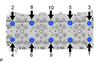
Uniformly loosen the 10 cylinder head set bolts in several passes in the sequence shown in the illustration. Then remove the 10 cylinder head set bolts and 6 cylinder head set bolt spacers.
Note
-
Cylinder head sub-assembly warpage or cracking could result from removing bolts in the incorrect order.
-
Be careful not to drop the cylinder head set bolt spacers into the cylinder head sub-assembly.
-
-
Lift the cylinder head sub-assembly from the ring pins on the cylinder block sub-assembly, and place the cylinder head sub-assembly on wooden blocks on a bench.
Note
Be careful not to damage the contact surfaces of the cylinder head sub-assembly and cylinder block sub-assembly.
Tech Tips
If the cylinder head sub-assembly is difficult to remove, use a screwdriver to pry between the cylinder head sub-assembly and cylinder block sub-assembly.
-
-
REMOVE CYLINDER HEAD GASKET
-
Remove the cylinder head gasket from the cylinder block sub-assembly.
-
-
INSPECT CYLINDER HEAD SET BOLT
-
w/ Washer:
-
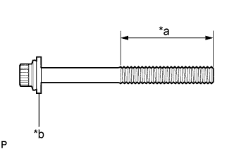
Text in Illustration *a Measuring Area *b Washer Using a vernier caliper, measure the thread outside diameter of the cylinder head set bolt.
Minimum diameter 11.4 mm (0.449 in.) If the diameter is less than the minimum, replace the cylinder head set bolt.
-
-
w/o Washer:
-
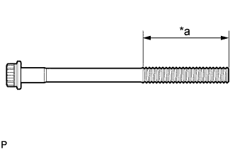
Text in Illustration *a Measuring Area Using a vernier caliper, measure the thread outside diameter of the cylinder head set bolt.
Minimum diameter 12.8 mm (0.504 in.) If the diameter is less than the minimum, replace the cylinder head set bolt and cylinder head set bolt spacer.
-
-