БЛОК ДВИГАТЕЛЯ РАЗБОРКА
Tech Tips
-
Thoroughly clean all parts to be assembled.
-
Before installing the parts, apply new engine oil to all sliding and rotating surfaces.
-
Replace all gaskets, O-rings and oil seals with new parts.
-
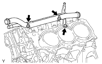
REMOVE NO. 1 ENGINE HANGER
-
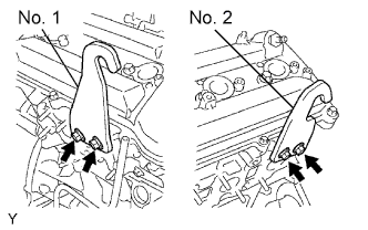
Remove the 2 bolts and No. 1 engine hanger.
-
-
REMOVE NO. 2 ENGINE HANGER
-
Remove the 2 bolts and No. 2 engine hanger.
-
-
REMOVE OIL DIPSTICK GUIDE
-
Remove the bolt and pull out the oil dipstick.
-
Remove the O-ring from the oil level gauge guide.
-
-
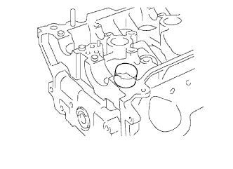
REMOVE CYLINDER BLOCK WATER DRAIN COCK
-
Remove the cylinder block water drain cock.
-
-
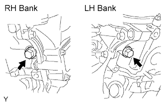
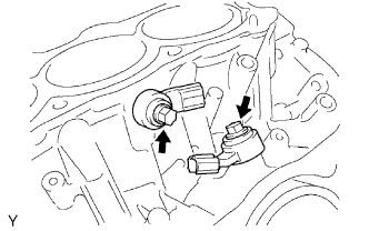
REMOVE VVT SENSOR
-
Remove the 2 bolts and 2 sensors.
-
-
REMOVE CRANKSHAFT POSITION SENSOR
-
Remove the bolt and crankshaft position sensor.
-
-
REMOVE OIL CONTROL VALVE FILTER
-
Remove the plug, filter and gasket from each cylinder head.
-
-
REMOVE CYLINDER HEAD COVER RH
-
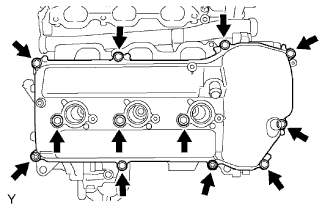
Remove the 10 bolts, 3 seal washers, 2 nuts, head cover and gasket.
-
-
REMOVE CYLINDER HEAD COVER LH
-
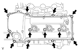
Remove the 10 bolts, 3 seal washers, 2 nuts, cylinder head cover and gasket.
-
Remove the ventilation valve from the cylinder head cover.
-
-
REMOVE CRANKSHAFT PULLEY
-
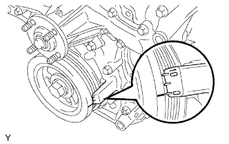
Turn the crankshaft pulley, and align its groove with the timing mark 0 of the timing chain cover.
-
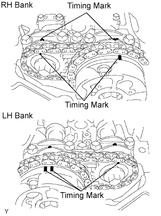
Check that the timing marks of the camshaft timing gears are aligned with the timing marks of the bearing cap as shown in the illustration.
If not, turn the crankshaft 1 revolution (360°) and align the timing marks as above.
-
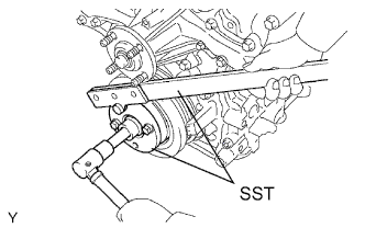
Using SST, hold the crankshaft pulley and loosen the pulley set bolt.
- SST
- 09213-54015 ( 91651-60855 )
- 09330-00021
-
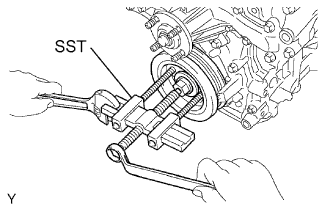
Using the pulley set bolt and SST, remove the crankshaft pulley.
- SST
- 09950-50013 ( 09951-05010, 09952-05010, 09953-05020, 09954-05030 )
-
-
REMOVE OIL PAN DRAIN PLUG
-
Remove the drain plug and gasket.
-
-
REMOVE NO. 2 OIL PAN
-
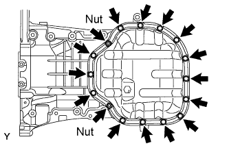
Remove the 14 bolts and 2 nuts.
-
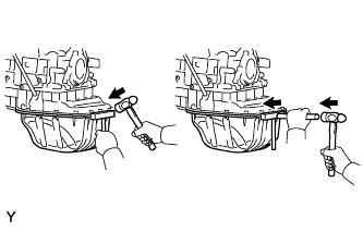
Insert the blade of an oil pan seal cutter between the oil pan and No. 2 oil pan, cut through the applied sealer and remove the No. 2 oil pan.
Note
-
Be careful not to damage the contact surface of the No. 2 oil pan and oil pan.
-
Be careful not to damage the No. 2 oil pan flange.
-
-
-
REMOVE OIL STRAINER
-
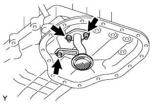
Remove the 2 nuts, oil strainer and gasket.
-
-
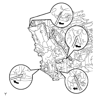
REMOVE NO. 1 OIL PAN
-
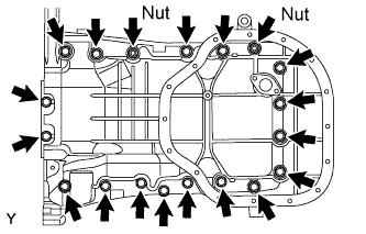
Remove 17 bolts and 2 nuts.
-
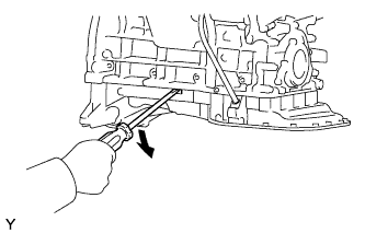
Using a screwdriver, remove the oil pan by prying between the oil pan and cylinder block in the sequence shown.
Note
Be careful not to damage the contact surfaces of the cylinder block and oil pan.
-
Remove the O-ring from the timing chain cover.
-
-
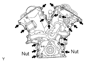
REMOVE WATER PUMP
-
Remove the 17 bolts, water pump and gasket.
-
-
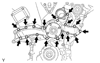
REMOVE TIMING CHAIN COVER
-
Remove the 15 bolts and 2 nuts.
-
Remove the timing chain cover by prying the portions between the timing chain cover and cylinder head or cylinder block with a screwdriver.
Note
Be careful not to damage the contact surfaces of the timing chain cover, cylinder block and cylinder head.
-
Remove the O-ring from the LH cylinder head.
-
-
REMOVE NO. 1 CHAIN TENSIONER
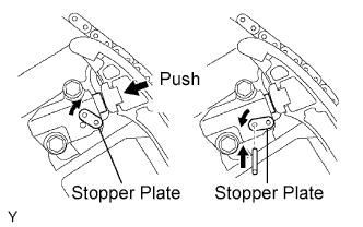
Note
-
Never rotate the crankshaft with the chain tensioner removed.
-
When rotating the camshaft with the timing chain removed, rotate the crankshaft counterclockwise 40° from the TDC before rotating it.
-
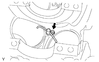
While rotating the stopper plate of the tensioner upward, push in the plunger of the chain tensioner as shown in the illustration.
-
While rotating the stopper plate of the tensioner downward, insert a bar of diameter of 3.5 mm (0.138 in.) into the holes in the stopper plate and tensioner to fix the stopper plate.
-
Remove the 2 bolts and chain tensioner.
-
-
REMOVE CHAIN TENSIONER SLIPPER
-
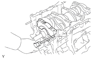
REMOVE NO. 1 IDLE GEAR
-
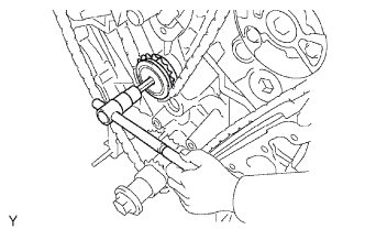
Using a 10 mm hexagon wrench, remove the No. 2 idle gear shaft, No. 1 idle gear and No. 1 idle gear shaft.
-
-
REMOVE NO. 2 VIBRATION DAMPER
-
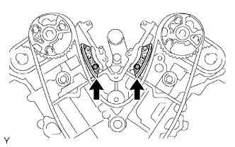
Remove the 2 chain vibration dampers.
-
-
REMOVE CHAIN
-
REMOVE CRANKSHAFT TIMING SPROCKET
-
REMOVE NO. 1 CHAIN VIBRATION DAMPER
-
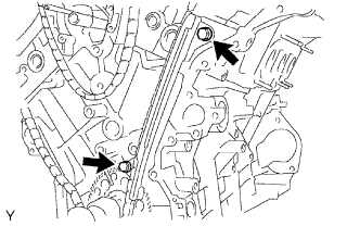
Remove the 2 bolts and No. 1 chain vibration damper.
-
-
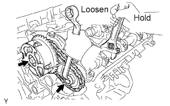
REMOVE CAMSHAFT TIMING GEARS AND NO. 2 CHAIN (RH BANK)
-
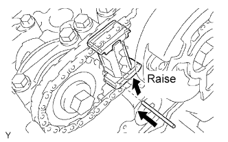
While raising up the No. 2 chain tensioner, insert a pin of diameter of 1.0 mm (0.039 in.) into the hole to fix it.
-
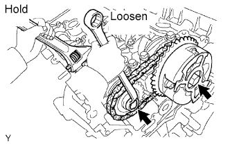
Hold the hexagonal portion of the camshaft with a wrench, and remove the 2 bolts, camshaft timing gear, camshaft timing gear assembly and No. 2 timing chain.
Note
-
Be careful not to damage the cylinder head and valve lifter with the wrench.
-
Do not disassemble the camshaft timing gear assembly.
-
-
-
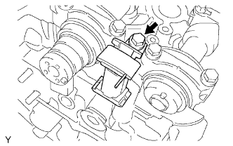
REMOVE NO. 2 CHAIN TENSIONER
-
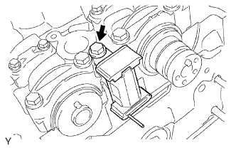
Remove the bolt and No. 2 chain tensioner.
-
-
REMOVE CAMSHAFT TIMING GEARS AND NO. 2 CHAIN (LH BANK)
-
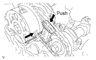
While pushing down the No. 3 chain tensioner, insert a pin of diameter of 1.0 mm (0.039 in.) into the hole to fix it.
-
Hold the hexagonal portion of the camshaft with a wrench, and remove the 2 bolts, camshaft timing gear, camshaft timing gear assembly and No. 2 timing chain.
Note
-
Be careful not to damage the cylinder head and valve lifter with the wrench.
-
Do not disassemble the camshaft timing gear assembly.
-
-
-
REMOVE NO. 3 CHAIN TENSIONER
-
Remove the bolt and No. 3 chain tensioner.
-
-
REMOVE CAMSHAFT
Note
As the thrust clearance of the camshaft is small, the camshaft must be kept level while it is being removed. If the camshaft is not kept level, the portion of the cylinder head which received the shaft thrust may crack or be damaged, causing the camshaft to seize or break. To avoid this, the following steps should be carried out.
-
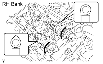
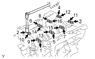
Remove the camshafts of the RH bank.
-
Rotate the camshafts counterclockwise using hexagonal portion of the each camshaft so that the cam lobes of the No. 1 cylinder may face as shown in the illustration.
-
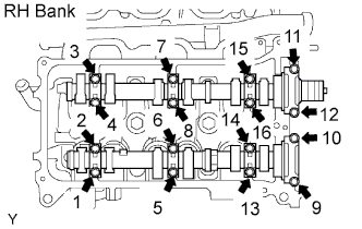
Uniformly loosen and remove the 16 bearing cap bolts in several passes, in the sequence shown.
-
Remove the 8 bearing caps and 2 camshafts.
-
-
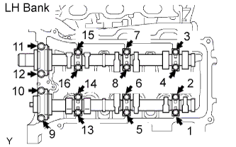
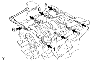
Remove the camshafts of the LH bank.
-
Uniformly loosen and remove the 16 bearing cap bolts in several passes, in the sequence shown.
-
Remove the 8 bearing caps and 2 camshafts.
-
-
-
REMOVE NO. 1 CAMSHAFT BEARING
-
REMOVE NO. 2 CAMSHAFT BEARING
-
REMOVE CYLINDER HEAD
-
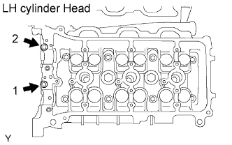
Remove the 2 cylinder head bolts on the LH cylinder head in several passes, in the sequence shown.
-
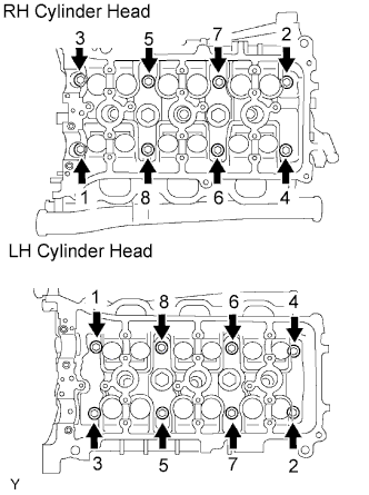
Using a 10 mm bi-hexagon wrench, uniformly loosen the 8 cylinder head bolts on each cylinder head, in several passes, in the sequence shown, then repeat for the other side as shown. Remove the 16 cylinder head bolts and plate washers.
Note
-
Be careful not to drop the plate washers into the cylinder head.
-
Head warpage or cracking could result from removing bolts in incorrect order.
-
-
Lift the cylinder head from the dowels on the cylinder block, and place the 2 cylinder heads on wooden blocks on a bench.
Note
Be careful not to damage the contact surfaces of the cylinder head and cylinder block.
Tech Tips
If the cylinder head is difficult to lift off, pry between the cylinder head and cylinder block with a screwdriver.
-
Remove the RH and LH cylinder head gaskets.
-
-
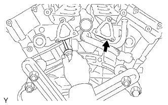
REMOVE NO. 1 WATER OUTLET PIPE
-
Separate the knock sensor wire.
-
Remove the bolt, 2 nuts and water outlet pipe.
-
-
REMOVE KNOCK SENSOR
-
Disconnect the knock sensor connectors.
-
Remove the 2 bolts and 2 knock sensors.
-
-
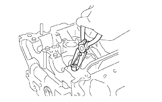
REMOVE ENGINE REAR OIL SEAL RETAINER
-
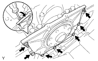
Remove the 5 bolts and 2 nuts.
-
Using a screwdriver, remove the oil seal retainer by prying the portions between the oil seal retainer and crankshaft bearing cap.
-
-
REMOVE VALVE LIFTER
Tech Tips
Arrange the valve lifter in the correct order.
-
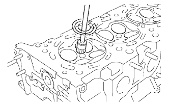
REMOVE VALVE
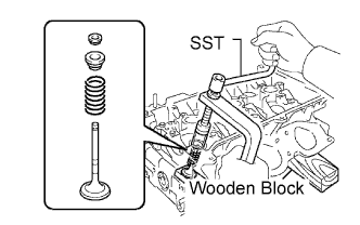
Tech Tips
Arrange the valves, inner compression springs, valve spring retainers and valve spring retainer rocks in the correct order.
-
Place the cylinder head on the wooden block.
-
Using SST, compress the inner compression spring and remove the 2 valve spring retainer locks.
- SST
- 09202-70020 ( 09202-00010 )
-
Remove the valve, inner compression spring and valve spring and valve spring retainer.
-
-
REMOVE VALVE SPRING SEAT
-
Using compressed air and a magnet hand, remove the valve spring seat by blowing air.
-
-
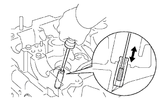
REMOVE VALVE STEM OIL SEAL
-
Using a needle-nose pliers, remove the valve stem oil seal.
-
-
CLEAN CYLINDER HEAD
-
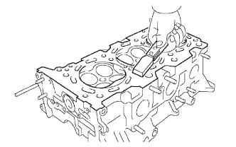
Using a gasket scraper, remove all the gasket material from the cylinder block contact surface.
Note
Be careful not to scratch the cylinder block contact surface.
-
Using a wire brush, remove all the carbon from the combustion chambers.
Note
Be careful not to scratch the combustion chambers.
-
Using a valve guide bushing brush and solvent, clean all the valve guide bushes.
-
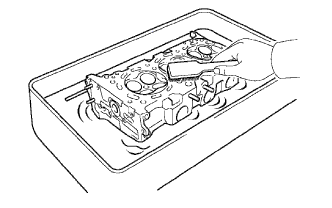
Using a soft brush and solvent, thoroughly clean the cylinder head.
-
-
CLEAN VALVE
-
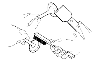
Using a gasket scraper, chip off any carbon from the valve head.
-
Using a wire brush, thoroughly clean the valve.
-
-
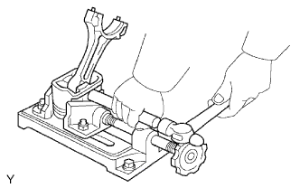
REMOVE CONNECTING ROD CAP
-
Using SST, remove the 2 connecting rod cap bols.
- SST
- 09011-38121
-
Remove the connecting rod cap.
-
-
REMOVE PISTON WITH CONNECTING ROD
-
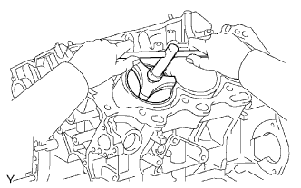
Using a ridge reamer, remove all the carbon from the top of the cylinder.
-
Push the piston, connecting rod assembly and upper bearing through the top of the cylinder block.
Tech Tips
-
Keep the bearings, connecting rod and cap together.
-
Arrange the piston and connecting rod assemblies in the correct order.
-
-
-
REMOVE PISTON RING SET
-
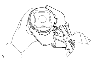
Using a piston ring expander, remove the 2 compression rings.
-
Remove the 2 side rails and oil ring by hand.
-
-
REMOVE PISTON PIN HOLE SNAP RING
-
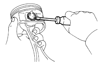
Using a small screwdriver, pry out the 2 snap rings.
-
-
REMOVE PISTON WITH PIN
-
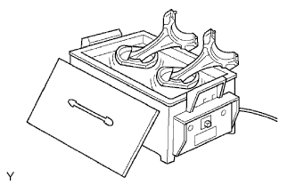
Gradually heat the piston to approximately 80°C (176°F).
-
Using a plastic-faced hammer and brass bar, lightly tap out the piston pin and remove the connecting rod.
Tech Tips
-
The piston and pin are a matched set.
-
Arrange the pistons, pins, rings, connecting rods and bearings in the correct order.
-
-
-
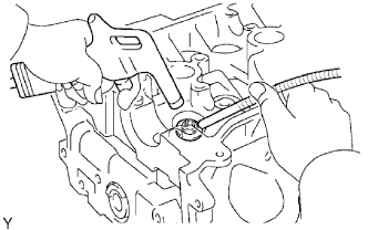
REMOVE CRANKSHAFT
-
Uniformly loosen and remove the 8 main bearing cap bolts and seal washers in the several passes, in the sequence shown.
-
Uniformly loosen and remove the 16 main bearing cap bolts in several passes, in the sequence shown.
-
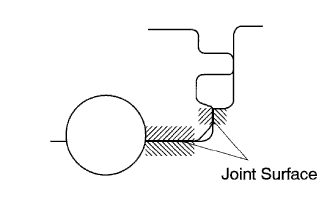
Using a screwdriver, pry out main bearing caps. Remove the 4 main bearing caps and lower bearings.
Note
-
Pull up the main bearing cap little by little to the right and the left by turns.
-
Be careful not to damage the joint surface of the cylinder block and the main bearing cap.
-
-
-
REMOVE CRANKSHAFT THRUST WASHER SET
-
REMOVE CRANKSHAFT BEARING
-
REMOVE OIL NOZZLE
-
Using a 5 mm socket hexagon wrench, remove the 3 oil nozzles.
-
-
REMOVE TAPER SCREW PLUG
Note
It is not necessary to remove a taper screw plug unless it is being replaced.