FRONT CONSOLE BOX DISASSEMBLY
CAUTION / NOTICE / HINT
Tech Tips
-
Use the same procedure as for the LHD and RHD vehicles.
-
The procedure listed below is for the LHD vehicles.
PROCEDURE
-
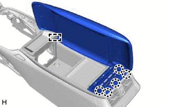
REMOVE CONSOLE BOX PLATE
-
Detach the clip and guide and remove the console box plate.
-
-
REMOVE CONSOLE BOX ILLUMINATION LIGHT ASSEMBLY
-
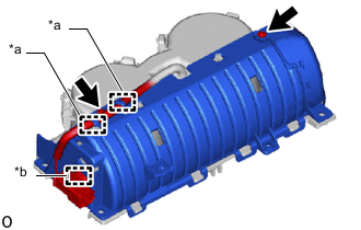
REMOVE CONSOLE BOX WIRE
-
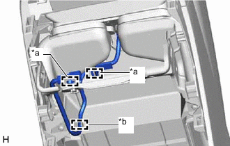
*a Clamp *b Hook Detach the clamp and hook and remove the console box wire.
-
-
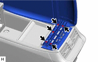
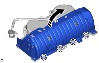
REMOVE UPPER NO. 2 BOX PLATE
Note
Perform this procedure only when replacing the rear console armrest assembly. Furthermore, always replace the No. 2 upper box plate with a new one when performing this procedure.
-
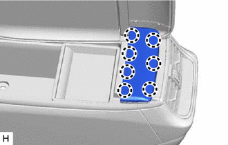
Detach the claw and remove the upper No. 2 box plate.
-
-
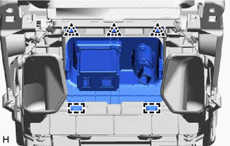
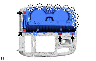
REMOVE REAR CONSOLE ARMREST ASSEMBLY
Note
Perform this procedure only when replacing the rear console armrest assembly.
-
Remove the 5 screws.
-
Detach the claw and guide and remove the rear console armrest assembly.
-
-
REMOVE REMOTE OPERATION CONTROLLER ASSEMBLY
-
REMOVE INTEGRATION CONTROL AND PANEL ASSEMBLY
-
REMOVE INSTRUMENT PANEL CUP HOLDER SUB-ASSEMBLY
-
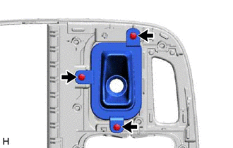
Remove the 4 screws.
-
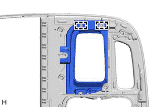
Detach the claw and remove the instrument panel cup holder sub-assembly.
-
-
REMOVE UPPER CONSOLE PANEL SUB-ASSEMBLY
-
*a Hook *b Clamp Remove the 2 screws.
-
Detach the clamp and hook.
-

Remove in this Direction Detach the claw and remove the cover in the direction of the arrow shown in the illustration.
Note
Do not completely remove the cover. Leave the cloth and cover connected.
-
Remove in this Direction 
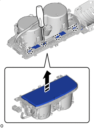
Protective Tape Using a thin-bladed screwdriver, detach the claw and remove the upper console panel sub-assembly in the direction indicated by the arrow shown in the illustration.
Tech Tips
Tape the thin-bladed screwdriver tip before use.
Note
Do not touch the spring and damper, as it will impact the operation of the instrument panel cup holder sub-assembly.
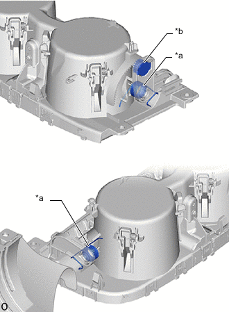
*a Spring *b Damper
-
-
REMOVE SHIFTING HOLE COVER SUB-ASSEMBLY
-
Remove the 3 screws and shifting hole cover sub-assembly.
-
-
REMOVE SHIFT POSITION INDICATOR
-
REMOVE SHIFTING HOLE BEZEL
-
Detach the guide and remove the shifting hole bezel.
-