WIPER AND WASHER SYSTEM TERMINALS OF ECU
-
CHECK WINDSHIELD WIPER RELAY ASSEMBLY (w/ Auto Wiper System)
-
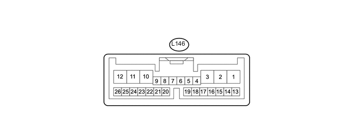
Disconnect the L146 windshield wiper relay assembly connector.
-
Measure the voltage and resistance according to the value(s) in the table below.
Terminal No. (Symbol) Wiring Color Terminal Description Condition Specified Condition L146-2 (IG) - Body ground B - Body ground Power switch on (IG) signal (Power source circuit) Power switch on (IG) 11 to 14 V Power switch off Below 1 V L146-8 (VR2) - L146-21 (VR1) W - L Adjusting volume circuit Windshield wiper switch adjusting ring* changed 0 to 231 Ω L146-12 (E) - Body ground W-B - Body ground Body ground Always Below 1 Ω L146-16 (WIG) - Body ground BE - Body ground Signal power source circuit Power switch on (IG) 11 to 14 V Power switch off Below 1 V L146-25 (W) - Body ground B - Body ground Front washer switch circuit Front washer switch on Below 1 Ω Front washer switch off 10 kΩ or higher Tech Tips
*: The rain sensor sensitivity can be adjusted by the windshield wiper switch adjusting ring.
If the result is not as specified, there may be a malfunction in the wire harness.
-
Reconnect the L146 windshield wiper relay assembly connector.
-
Measure the voltage according to the value(s) in the table below.
Terminal No. (Symbol) Wiring Color Terminal Description Condition Specified Condition L146-1 (+SM) - Body ground G - Body ground Front wiper motor position detection signal Front wiper motor in low or high operation Below 1 V ←→ 11 to 14 V Front wiper motor off Below 1 V L146-3 (C1) - L146-5 (C0) V - Y Front wiper switch AUTO signal circuit Power switch on (IG), front wiper switch in AUTO Below 1 V Power switch on (IG), front wiper switch off 11 to 14 V L146-10 (+1) - Body ground G - Body ground Front wiper motor low speed signal circuit Front wiper motor in low operation 11 to 14 V Front wiper motor off Below 1 V L146-11 (+2) - Body ground L - Body ground Front wiper motor high speed signal circuit Front wiper motor in high operation 11 to 14 V Front wiper motor off Below 1 V L146-14 (MPX1) - Body ground Y - Body ground Rain sensor signal Power switch on (IG) Pulse generation L146-24 (SPD) - Body ground W - Body ground Speed signal Power switch on (IG), wheel being rotated Pulse generation
(See Waveform 1)
L146-25 (W) - Body ground B - Body ground Front washer switch circuit Power switch on (IG), front washer switch on Below 1 V Power switch on (IG), front washer switch off 11 to 14 V If the result is not as specified, the windshield wiper relay assembly may have a malfunction.
-
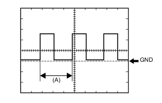
Waveform 1 (Reference):
Item Condition Tool setting 5 V/DIV., 20 ms./DIV. Vehicle condition Wheel being rotated Tech Tips
When the system is functioning normally, one wheel revolution generates 4 pulses. As the vehicle speed increases, the width indicated by (A) in the illustration narrows.
-
-
-
CHECK HEADLIGHT CLEANER CONTROL RELAY
-
Disconnect the A44 headlight cleaner control relay connector.
-
Measure the voltage and resistance according to the value(s) in the table below.
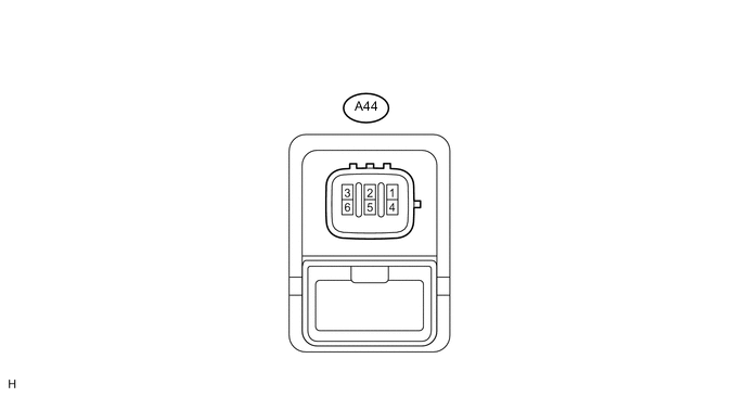
Terminal No. (Symbol) Wiring Color Terminal Description Condition Specified Condition A44-2 (H) - A44-4 (E) LG - W-B Headlight cleaner switch operation signal Light control switch off and headlight cleaner switch off Below 1 V Light control switch off and headlight cleaner switch on 11 to 14 V A44-3 (IG) - A44-4 (E) B - W-B Power switch on (IG) signal (Power source circuit) Power switch off Below 1 V Power switch on (IG) 11 to 14 V A44-4 (E) - Body ground W-B - Body ground Body ground Always Below 1 Ω A44-5 (FRWA) - A44-4 (E) R - W-B Front washer switch signal Power switch on (IG)
Front washer switch off
11 to 14 V Power switch on (IG)
Front washer switch on
Below 1 V A44-6 (PB) - A44-4 (E) B - W-B Headlight clear motor operation signal Power switch off 11 to 14 V If the result is not as specified, there may be a malfunction in the wire harness.
-
-
CHECK INSTRUMENT PANEL JUNCTION BLOCK ASSEMBLY AND MAIN BODY ECU (MULTIPLEX NETWORK BODY ECU)
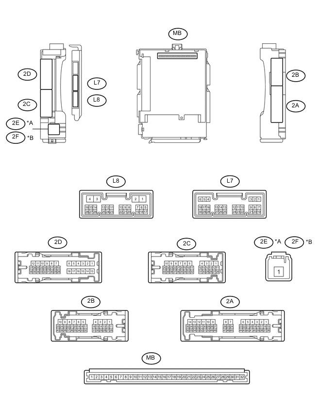
Text in Illustration *A for LHD *B for RHD
-
Measure the voltage according to the value(s) in the table below.
Terminal No. (Symbol) Wiring Color Terminal Description Condition Specified Condition 2C-35 - Body ground L - Body ground Low beam headlight signal Power switch on (IG), light control switch in head position Below 1 V Power switch on (IG), light control switch off 4.2 V or higher
-