AIR CONDITIONING SYSTEM (for Automatic Air Conditioning System) Power Heater Switch Circuit
DESCRIPTION
The power heater operates when the heater switch assembly is on and the following conditions are met:
-
Ignition switch is ON.
-
Air inlet control damper position is FRESH.
-
Blower motor switch is in any position other than OFF.
-
Air mix damper position is Max. HOT.
-
Engine coolant temperature is below 65°C (149°F).
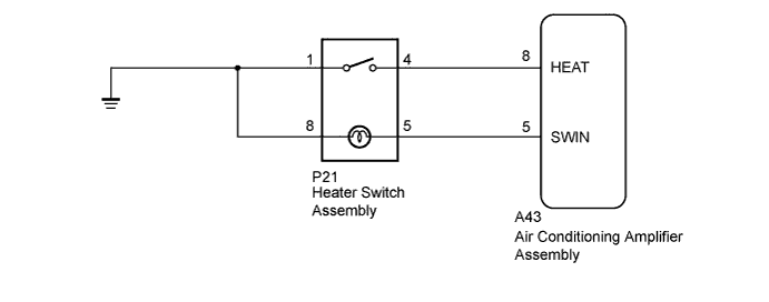
WIRING DIAGRAM
INSPECTION PROCEDURE
PROCEDURE
-
INSPECT HEATER SWITCH ASSEMBLY
-
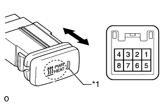
Text in Illustration *1 Indicator Light Remove the heater switch assembly Click here.
-
Measure the resistance according to the value(s) in the table below.
Standard Resistance Tester Connection Switch Condition Specified Condition 4 - 1 Heater switch assembly on Below 1 Ω 4 - 1 Heater switch assembly off 10 kΩ or higher -
Apply battery voltage to the switch connector and check that the indicator light illuminates.
OK Measurement Connection Specified Condition Battery positive (+) → Terminal 5 Indicator light illuminates Battery negative (-) → Terminal 8
NG 
REPLACE HEATER SWITCH ASSEMBLY Click here
OK 
-
-
CHECK HARNESS AND CONNECTOR (HEATER SWITCH - AIR CONDITIONING AMPLIFIER AND BODY GROUND)
-
Disconnect the P21 heater switch assembly connector.
-
Disconnect the A43 air conditioning amplifier assembly connector.
-
Measure the resistance according to the value(s) in the table below.
Standard Resistance Tester Connection Condition Specified Condition P21-4 - A43-8 (HEAT) Always Below 1 Ω P21-5 - A43-5 (SWIN) P21-4 - Body ground Always 10 kΩ or higher P21-5 - Body ground P21-1 - Body ground Always Below 1 Ω P21-8 - Body ground
NG
REPAIR OR REPLACE HARNESS OR CONNECTOR
OK 
PROCEED TO NEXT SUSPECTED AREA SHOWN IN PROBLEM SYMPTOMS TABLE Click here
-