BRAKE CONTROL SYSTEM
-
CONSTRUCTION
-
The 2 master cylinder pressure sensors, 4 wheel cylinder pressure sensors, and an accumulator pressure sensor are installed in the brake actuator assembly.
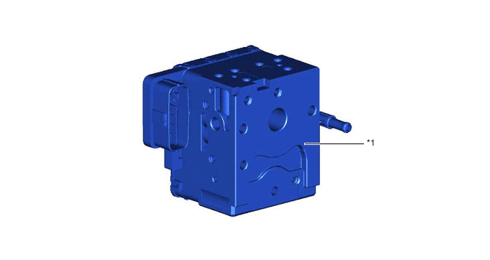
*1 Brake Actuator Assembly - - -
The construction of the brake actuator assembly, and the role of each part, is as follows:

*1 Master Cylinder Cut Solenoid Valve (2-position Type)
-
When the brake pedal is depressed, this valve cuts the hydraulic passage between the brake master cylinder sub-assembly and its wheel cylinder.
-
When the brake pedal is not depressed or a failure occurs in the hydraulic power source portion, the valves open to maintain the hydraulic passage to the front wheel cylinders and ensure braking.
-
When a failure occurs, a greater effort than normal is required to depress the brake pedal.
*2 Pressure Application Valve (Linear Type) These valves, which are controlled by the skid control ECU assembly, regulate the fluid pressure from the accumulator in order to hold or increase the fluid pressure to the wheel cylinders. *3 Pressure Reduction Valve (Linear Type) These valves, which are controlled by the skid control ECU assembly, regulate the fluid pressure in order to reduce the fluid pressure to the wheel cylinders. *4 Relief Valve Returns the brake fluid to the reservoir tank to prevent excessive pressure if the pump operates continuously due to a malfunction of the accumulator pressure sensor. *5 Master Cylinder Pressure Sensor The master cylinder pressure sensor converts the fluid pressure generated by the brake master cylinder sub-assembly into electrical signals and transmits them to the skid control ECU assembly. Accordingly, the skid control ECU assembly determines the braking force required by the driver. *6 Wheel Cylinder Pressure Sensor These sensors detect the fluid pressure that acts on their respective wheel cylinders and transmits the pressure to the skid control ECU assembly to provide feedback. Accordingly, the skid control ECU assembly can monitor the fluid pressure of the wheel cylinders and control the pressure application solenoid valves and the pressure reduction solenoid valves, in order to achieve the optimal wheel cylinder pressures. *7 Accumulator Pressure Sensor The accumulator pressure sensor constantly monitors the brake fluid pressure in the accumulator and transmits a signal to the skid control ECU assembly. Accordingly, the skid control ECU assembly controls the pump motor. -
-
The brake actuator assembly is constructed with the following hydraulic circuit:
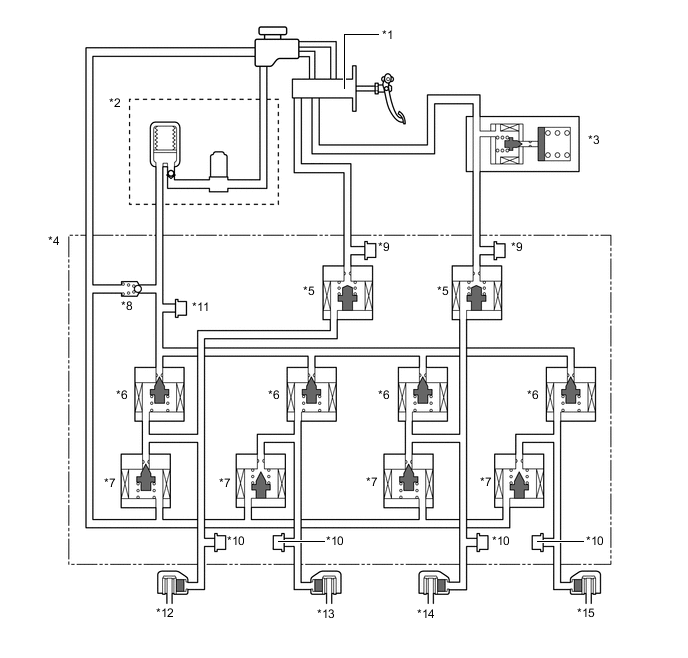
*1 Brake Master Cylinder Sub-assembly *2 Brake Booster Pump Assembly
-Accumulator
-Pump
*3 Brake Stroke Simulator Cylinder Sub-assembly *4 Brake Actuator Assembly *5 Master Cylinder Cut Solenoid Valve (2-position Type) *6 Pressure Application Valve (Linear Type) *7 Pressure Reduction Valve (Linear Type) *8 Relief Valve *9 Master Cylinder Pressure Sensor *10 Wheel Cylinder Pressure Sensor *11 Accumulator Pressure Sensor *12 Front Brake Caliper (Right Side) *13 Rear Brake Caliper (Left Side) *14 Front Brake Caliper (Left Side) *15 Rear Brake Caliper (Right Side) - -
-