ENGINE UNIT DISASSEMBLY
PROCEDURE
REMOVE OIL FILLER CAP SUB-ASSEMBLY
-
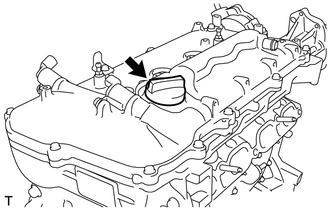
Remove the oil filler cap sub-assembly.
-
REMOVE OIL FILLER CAP GASKET
-
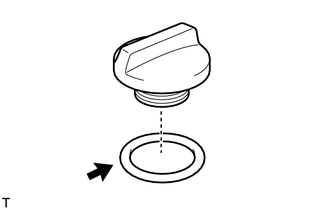
Remove the oil filler cap gasket.
-
REMOVE ENGINE COVER JOINT
-
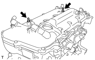
Remove the 2 engine cover joints.
-
REMOVE SPARK PLUG
REMOVE CAMSHAFT POSITION SENSOR
for Intake Side:
for Exhaust Side:
REMOVE CAMSHAFT TIMING OIL CONTROL VALVE ASSEMBLY
for Intake Side:
for Exhaust Side:
REMOVE CRANKSHAFT POSITION SENSOR
REMOVE ENGINE OIL PRESSURE SWITCH ASSEMBLY
REMOVE KNOCK SENSOR
REMOVE ENGINE COOLANT TEMPERATURE SENSOR
REMOVE CYLINDER HEAD COVER SUB-ASSEMBLY
-
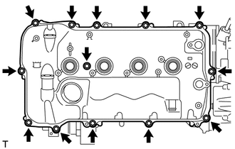
Remove the 13 bolts, seal washer and cylinder head cover sub-assembly.
-
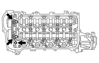
Remove the 3 gaskets from the camshaft bearing cap.
Note:As gaskets may stick to the cylinder head cover sub-assembly, be careful not to drop any of the gaskets into the engine when removing the cylinder head cover sub-assembly.
-
REMOVE CYLINDER HEAD COVER GASKET
-
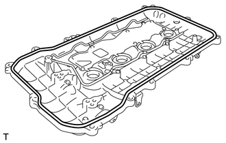
Remove the cylinder head cover gasket.
-
REMOVE SPARK PLUG TUBE GASKET
-
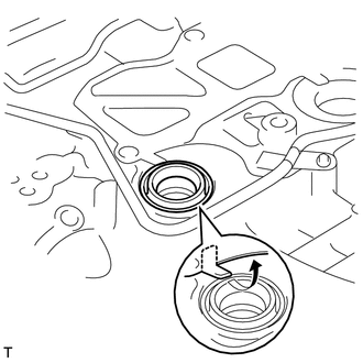
Pry up the 4 claws of the ventilation baffle plate.
Note:Do not deform the claws of the ventilation baffle plate more than necessary.
-
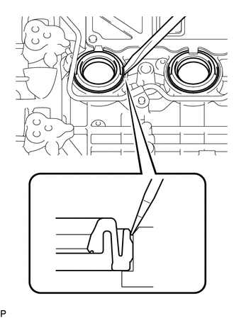
Using a screwdriver as shown in the illustration, deform each spark plug tube gasket inwards and remove the 4 spark plug tube gaskets from cylinder head cover sub-assembly.
Note:As much as possible prevent the spark plug tube gaskets from being deformed.
The removed spark plug tube gaskets will be used when reinstalling the new spark plug tube gaskets.
Do not damage the cylinder head cover sub-assembly.
Make sure not to damage the spark plug tube gasket and cylinder head cover sub-assembly when inserting the screwdriver in the joint area.
Tip:If the cylinder head cover sub-assembly is damaged, smooth the surface with 400-grid sandpaper.
-
REMOVE OIL FILTER
REMOVE UNION
-
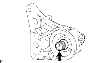
for Oil Filter Sub-assembly Type:
Using a 12 mm hexagon wrench, remove the union.
-
SET NO. 1 CYLINDER TO TDC/COMPRESSION
-
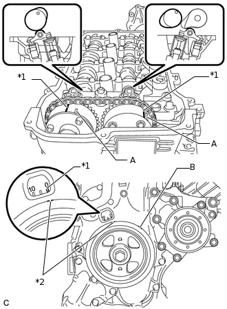
*1
Timing Mark
*2
Notch
Turn the crankshaft pulley until its notch and timing mark "0" of the timing chain cover are aligned.
Tip:A in the illustration is not the timing mark.
Do not align the timing mark with notch B on the crankshaft pulley in the illustration.
Check that the timing marks on both the camshaft timing exhaust gear and camshaft timing gear are facing upward as shown in the illustration.
Tip:If the marks are not as shown, turn the crankshaft 1 complete revolution (360°) and align the marks as specified above.
-
REMOVE CRANKSHAFT PULLEY
REMOVE NO. 1 CHAIN TENSIONER ASSEMBLY
-
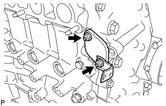
Remove the 2 nuts, bracket, No. 1 chain tensioner assembly and gasket.
Note:Do not turn the crankshaft without the No. 1 chain tensioner installed.
-
REMOVE ENGINE MOUNTING BRACKET STUD BOLT
-
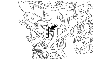
Remove the engine mounting bracket stud bolt.
-
REMOVE TIMING CHAIN COVER SUB-ASSEMBLY
REMOVE TIMING CHAIN COVER OIL SEAL
REMOVE WATER INLET HOUSING
-
Remove the 3 bolts, water inlet housing and gasket.
-
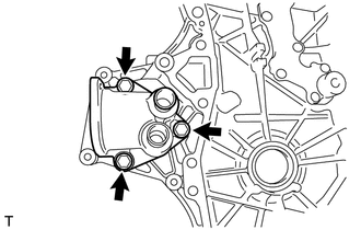
REMOVE NO. 1 GENERATOR BRACKET
-
Remove the 4 bolts and No. 1 generator bracket.
-
REMOVE CHAIN TENSIONER SLIPPER
-
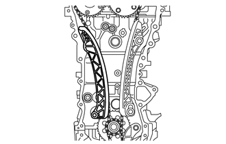
Remove the chain tensioner slipper from the cylinder block assembly.
-
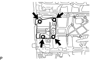
REMOVE NO. 1 CHAIN VIBRATION DAMPER
-
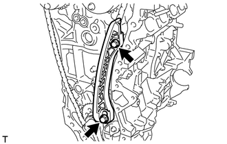
Remove the 2 bolts and No. 1 chain vibration damper.
-
REMOVE CHAIN SUB-ASSEMBLY
-
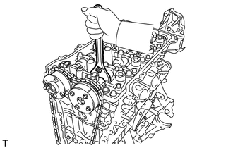
Hold the hexagonal portion of the camshaft with a wrench and turn the camshaft timing gear counterclockwise to loosen the chain sub-assembly between the camshaft timing gears.
With the chain sub-assembly loosened, release the chain sub-assembly from the camshaft timing gear and place it on the camshaft timing gear.
Tip:Be sure to release the chain sub-assembly from the sprocket completely.
Turn the camshaft clockwise to return it to the original position and remove the chain sub-assembly.
-
REMOVE CRANKSHAFT TIMING SPROCKET
REMOVE NO. 2 CHAIN SUB-ASSEMBLY
REMOVE NO. 1 CRANKSHAFT POSITION SENSOR PLATE
-
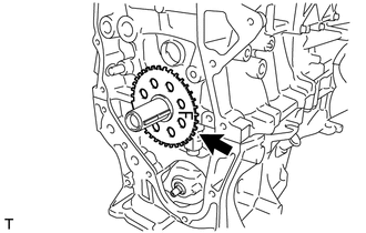
Remove the No. 1 crankshaft position sensor plate.
-
REMOVE CRANKSHAFT TIMING GEAR KEY
-
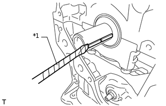
*1
Protective Tape
Using a screwdriver, remove the 2 crankshaft timing gear keys.
Tip:Tape the screwdriver tip before use.
-
INSPECT CAMSHAFT TIMING GEAR ASSEMBLY
INSPECT CAMSHAFT TIMING EXHAUST GEAR ASSEMBLY
REMOVE CAMSHAFT TIMING GEAR ASSEMBLY
REMOVE CAMSHAFT TIMING EXHAUST GEAR ASSEMBLY
REMOVE VALVE ROCKER ARM LOST MOTION DAMPER SUB-ASSEMBLY
INSTALL VALVE ROCKER ARM LOST MOTION DAMPER SUB-ASSEMBLY
REMOVE CAMSHAFT HOUSING SUB-ASSEMBLY
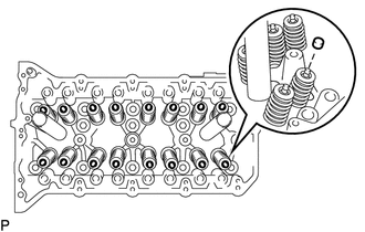
REMOVE CONTINUOUSLY VARIABLE VALVE LIFT CONTROLLER ASSEMBLY
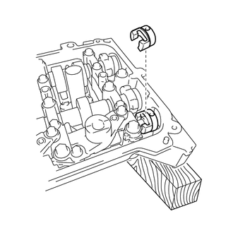
-
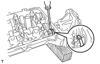
Using a screwdriver, slide the control actuator clip from the control actuator connector.
Note:Slide only the upper part of the control actuator clip, as the straight pin may fall if the control actuator clip is completely removed.
-
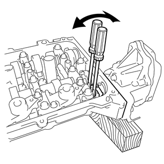
Using 2 screwdrivers, lightly pry the control actuator connector to make a space between the continuously variable valve lift controller assembly and camshaft housing sub-assembly.
Note:Do not forcefully pry the control actuator connector.
Do not damage the camshaft housing sub-assembly and camshaft bearing cap.
-
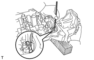
Using a magnet hand, remove the straight pin from the control actuator connector.
Tip:The straight pin can be removed by utilizing the space between the continuously variable valve lift controller assembly and camshaft housing sub-assembly to move the continuously variable valve lift controller assembly so that there is no load on the straight pin.
-
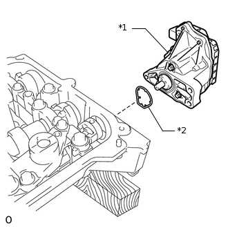
*1
Continuously Variable Valve Lift Controller Assembly
*2
O-Ring
Remove the bolt and the continuously variable valve lift controller assembly from the camshaft housing sub-assembly.
Remove the O-ring from the continuously variable valve lift controller assembly.
Note:The O-ring may remain on the camshaft housing side. Be sure to always remove it.
-
Remove the valve lift control actuator connector from the valve rocker shaft.
-
REMOVE NO. 1 VALVE ROCKER ARM SUB-ASSEMBLY
-
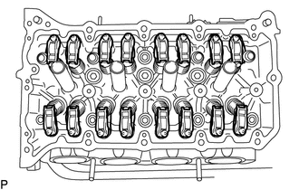
Remove the 16 No. 1 valve rocker arm sub-assemblies.
Tip:Arrange the removed parts in the correct order.
-
REMOVE VALVE LASH ADJUSTER ASSEMBLY
-
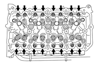
Remove the 16 valve lash adjuster assemblies from the cylinder head sub-assembly.
Tip:Arrange the removed parts in the correct order.
-
REMOVE VALVE STEM CAP
-
Remove the 16 valve stem caps.
Tip:Arrange the removed parts in the correct order.
-
REMOVE CYLINDER HEAD SUB-ASSEMBLY
REMOVE CAMSHAFT HOUSING STRAIGHT PIN
Note:It is not necessary to remove a straight pin unless it is being replaced.
REMOVE CYLINDER HEAD GASKET
REMOVE PCV VALVE SUB-ASSEMBLY
REMOVE OIL PAN DRAIN PLUG
-
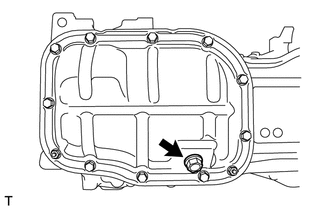
Remove the oil pan drain plug and gasket.
-
REMOVE NO. 2 OIL PAN SUB-ASSEMBLY
REMOVE OIL PUMP ASSEMBLY
REMOVE ENGINE REAR OIL SEAL
REMOVE STIFFENING CRANKCASE ASSEMBLY
-
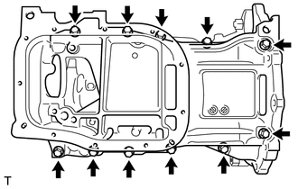
Uniformly loosen and remove the 11 bolts.
-
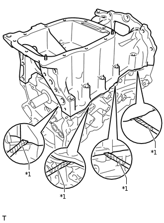
*1
Protective Tape
Using a screwdriver, remove the stiffening crankcase assembly by prying between the stiffening crankcase assembly and cylinder block assembly.
Note:Be careful not to damage the contact surfaces of the stiffening crankcase assembly and cylinder block assembly.
Tip:Tape the screwdriver tip before use.
-
REMOVE NO. 1 TAPER SCREW PLUG
-
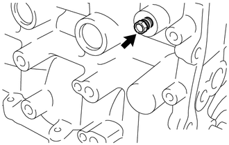
Remove the No. 1 taper screw plug.
-
REMOVE STUD BOLT
Note:If a stud bolt is deformed or its threads are damaged, replace it.
REMOVE STIFFENING CRANKCASE RING PIN
Note:It is not necessary to remove a stiffening crankcase ring pin unless it is being replaced.