FUEL PUMP(for High Pressure) REMOVAL
CAUTION / NOTICE / HINT
The necessary procedures (adjustment, calibration, initialization or registration) that must be performed after parts are removed and installed, or replaced during fuel pump assembly removal/installation are shown below.
| Replaced Part or Performed Procedure | Necessary Procedure | Effect/Inoperative Function when Necessary Procedure not Performed | Link |
|---|---|---|---|
| Battery terminal is disconnected/reconnected | Perform steering sensor zero point calibration | Lane departure alert system (w/ Steering Control) | |
| Pre-collision system | |||
| Memorize steering angle neutral point | Parking assist monitor system | ||
| Panoramic view monitor system | |||
|
Inspection after repair |
|
Click here for A25A-FKS (w/ Canister Pump Module) Click here for A25A-FKS (w/ Canister Pump Module) |
CAUTION:
-
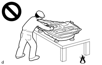
Never perform work on fuel system components near any possible ignition sources.
-
Vaporized fuel could ignite, resulting in a serious accident.
-
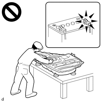
Do not perform work on fuel system components without first disconnecting the cable from the negative (-) battery terminal.
-
Sparks could cause vaporized fuel to ignite, resulting in a serious accident.
-
To prevent serious injury due to fuel spray from the high-pressure fuel lines, always discharge fuel system pressure before removing any fuel system components.
Note
This procedure includes the removal of small-head bolts. Refer to Small-Head Bolts of Basic Repair Hint to identify the small-head bolts.
PROCEDURE
-
PRECAUTION
Note
After turning the ignition switch off, waiting time may be required before disconnecting the cable from the negative (-) battery terminal. Therefore, make sure to read the disconnecting the cable from the negative (-) battery terminal notices before proceeding with work.
-
DISCHARGE FUEL SYSTEM PRESSURE
-
DISCONNECT CABLE FROM NEGATIVE BATTERY TERMINAL
Note
When disconnecting the cable, some systems need to be initialized after the cable is reconnected.
-
REMOVE INTAKE MANIFOLD
-
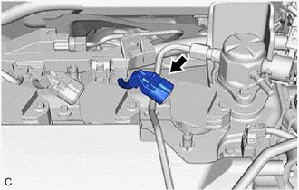
DISCONNECT FUEL TUBE SUB-ASSEMBLY
-
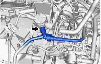
Disconnect the fuel tube sub-assembly from the fuel pump assembly.
-
-
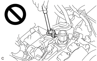
REMOVE NO. 1 FUEL PIPE SUB-ASSEMBLY
-
Disconnect the No. 1 ignition coil connector.
-
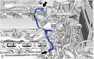
Using a 17 mm union nut wrench, loosen the 2 union nuts of the No. 1 fuel pipe sub-assembly.
-
Loosen the 2 bolts of the fuel pump assembly.
-
Remove the No. 1 fuel pipe sub-assembly from the fuel delivery pipe and fuel pump assembly.
-
-
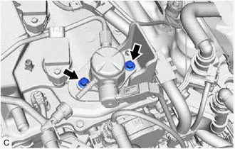
REMOVE FUEL PUMP ASSEMBLY
Note
When replacing the fuel pump assembly, it is necessary to replace the No. 1 fuel pipe sub-assembly with a new one.
-
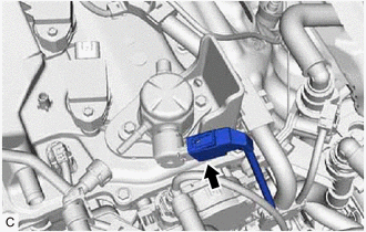
Disconnect the fuel pump assembly connector.
-
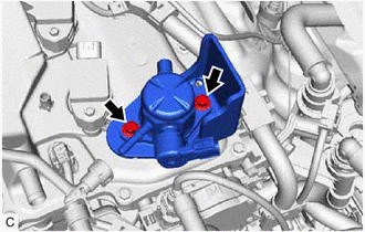
Remove the 2 bolts, fuel pump assembly and fuel pump flange from the cylinder head cover sub-assembly.
-
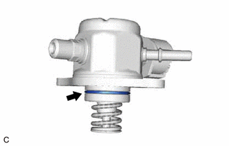
Remove the O-ring from the fuel pump assembly.
-
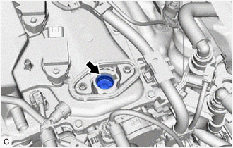
Remove the fuel pump lifter assembly from the fuel pump lifter guide.
-
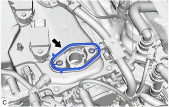
Remove the fuel pump spacer gasket from the cylinder head cover sub-assembly.
-