FUEL INJECTOR INSTALLATION
CAUTION / NOTICE / HINT
Perform "Inspection After Repairs" after replacing the fuel injector assembly.
for K111, K111F:
except K111, K111F:
PROCEDURE
INSTALL FUEL INJECTOR ASSEMBLY
Tip:Perform "Inspection After Repairs" after replacing the fuel injector assembly.
for K111, K111F:
except K111, K111F:
-
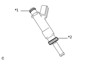
*1
O-Ring
*2
Injector Vibration Insulator
Install a new injector vibration insulator and a new O-ring to each fuel injector assembly.
Apply a light coat of gasoline or spindle oil to the O-ring of the fuel injector assembly.
-
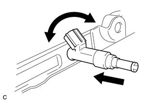
While turning the fuel injector assembly left and right, install it to the fuel delivery pipe sub-assembly.
Note:Do not twist the O-ring.
After installing the fuel injectors, check that they turn smoothly. If not, replace the O-ring with a new one.
INSTALL FUEL DELIVERY PIPE SUB-ASSEMBLY
-
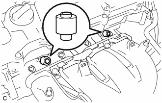
Install the 2 No. 1 delivery pipe spacers to the cylinder head.
Note:Install the No. 1 delivery pipe spacers in the correct direction.
Install the fuel delivery pipe sub-assembly with the 4 fuel injector assemblies, and then temporarily install the 2 bolts.
Note:Do not drop the fuel injector assemblies when installing the fuel delivery pipe sub-assembly.
Check that the fuel injector assemblies rotate smoothly after installing the fuel delivery pipe sub-assembly.
Tighten the 2 bolts to the specified torque.
21 N*m
214 kgf*cm
15 ft.*lbf
Install the bolt to secure the fuel delivery pipe sub-assembly.
21 N*m
214 kgf*cm
15 ft.*lbf
Install the wire harness bracket with the bolt.
8.0 N*m
82 kgf*cm
71 in.*lbf
-
CONNECT FUEL TUBE SUB-ASSEMBLY
Connect the fuel tube sub-assembly, and then install a new No. 2 fuel pipe clamp.
INSTALL VACUUM SURGE TANK
-
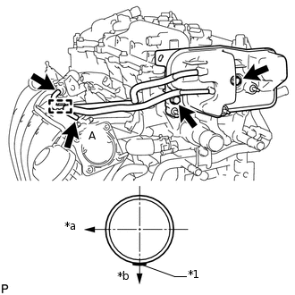
*1
Paint Mark
*a
Front Side of Vehicle
*b
LH Side
Install the vacuum surge tank with the 2 bolts.
21 N*m
214 kgf*cm
15 ft.*lbf
Connect the 2 air hoses to the purge VSV and intake manifold and attach the clamp.
Tip:Connect the air hose labeled A so that the paint mark is positioned as shown in the illustration.
-
INSTALL AIR TUBE
Install the air tube with the 2 bolts.
10 N*m
102 kgf*cm
7 ft.*lbf
Connect the No. 1 fuel vapor feed hose to the air tube.
Connect the No. 1 vacuum transmitting hose to the air tube and slide the clamp to secure it.
Connect the union to connector tube hose to the air tube and slide the clamp to secure it.
Connect the fuel vapor feed hose to the purge VSV and slide the clamp to secure it.
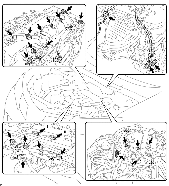
CONNECT ENGINE WIRE
Attach the 9 clamps and connect the 18 connectors.
Connect the engine wire with the 3 bolts and 3 nuts.
for bolt A
7.7 N*m
79 kgf*cm
68 in.*lbf
for bolt B and nut
8.4 N*m
86 kgf*cm
74 in.*lbf
INSTALL BATTERY TRAY
INSTALL BATTERY
INSTALL BATTERY CLAMP SUB-ASSEMBLY
INSTALL AIR CLEANER CASE SUB-ASSEMBLY
INSTALL AIR CLEANER CAP SUB-ASSEMBLY
CONNECT CABLE TO NEGATIVE BATTERY TERMINAL
Note:When disconnecting the cable, some systems need to be initialized after the cable is reconnected.
INSPECT FOR FUEL LEAK
Make sure that there are no fuel leaks after performing maintenance on the fuel system.
Connect the GTS to the DLC3.
Turn the ignition switch to ON, and GTS on.
Note:Do not start the engine.
Enter the following menus: Powertrain / Engine and ECT / Active Test / Control the Fuel Pump / Speed.
Powertrain > Engine and ECT > Active Test
Tester Display
Control the Fuel Pump / Speed
Check that there are no leaks from the fuel system.
Turn the ignition switch off.
Disconnect the GTS from the DLC3.
INSTALL NO. 2 CYLINDER HEAD COVER