CLUTCH MASTER CYLINDER(for LHD) INSTALLATION
PROCEDURE
INSTALL CLUTCH MASTER CYLINDER PUSH ROD CLEVIS
-
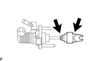
Install the lock nut to the clutch master cylinder assembly.
Install the clutch master cylinder push rod clevis to the clutch master cylinder assembly.
-
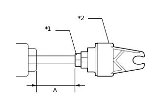
*1
Lock Nut
*2
Clutch Master Cylinder Push Rod Clevis
Tighten the lock nut and check that dimension A is the same as the dimension A that has been measured.
12 N*m
122 kgf*cm
9 ft.*lbf
Note:When tightening the lock nut, be sure to hold the clevis in place by its square portion.
-
INSTALL CLUTCH MASTER CYLINDER BRACKET
Install the clutch master cylinder bracket to the clutch master cylinder assembly.
INSTALL CLUTCH MASTER CYLINDER ASSEMBLY
Install the clutch master cylinder assembly with the 2 nuts.
13 N*m
133 kgf*cm
10 ft.*lbf
CONNECT CLUTCH MASTER CYLINDER PUSH ROD CLEVIS WITH HOLE PIN
CONNECT CLUTCH MASTER CYLINDER TO FLEXIBLE HOSE TUBE
Using a union nut wrench, connect the clutch master cylinder to flexible hose tube.
15 N*m
153 kgf*cm
11 ft.*lbf
Note:Use the formula to calculate special torque values for situations where a union nut wrench is combined with a torque wrench (Click hereClick hereClick here).
CONNECT CLUTCH RESERVOIR TUBE
Connect the clutch reservoir tube to the clutch master cylinder assembly, and slide the clamp to secure it.
Note:Connect the clutch reservoir tube so that it will not be twisted.
Face the yellow mark upward.
INSTALL LOWER NO. 1 INSTALL INSTRUMENT PANEL AIRBAG ASSEMBLY (w/ Driver Side Knee Airbag)
INSTALL LOWER INSTRUMENT PANEL FINISH PANEL (w/o Driver Side Knee Airbag)
INSTALL NO. 1 INSTRUMENT PANEL UNDER COVER SUB-ASSEMBLY (w/o Driver Side Knee Airbag)
INSTALL COWL BODY MOUNTING REINFORCEMENT LH
Install the cowl body mounting reinforcement LH with the 2 nuts.
50 N*m
510 kgf*cm
37 ft.*lbf
INSTALL OUTER COWL TOP PANEL SUB-ASSEMBLY
INSTALL WINDSHIELD WIPER MOTOR ASSEMBLY
INSTALL INJECTOR DRIVER
INSPECT SRS WARNING LIGHT
BLEED CLUTCH PIPE LINE
for 1AD-FTV:
for 2AD-FTV:
for 2AR-FE:
for 3ZR-FE:
for 3ZR-FAE:
CHECK BRAKE FLUID
Tip:Check for leakage in the brake system.
Check for leakage in the clutch system.
CHECK FLUID LEVEL IN RESERVOIR
INSPECT AND ADJUST CLUTCH PEDAL SUB-ASSEMBLY