POWER MIRROR CONTROL SYSTEM Power Mirrors do not Return to Memorized Position
| DTC Code | DTC Name |
|---|---|
| Power Mirrors do not Return to Memorized Position |
SYSTEM DESCRIPTION
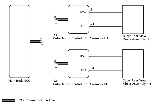
If the M1 or M2 seat memory switch is pressed, the outer mirror control ECU assembly LH detects the seat memory switch status and sends the switch signal to the main body ECU (multiplex network body ECU) via CAN communication. The main body ECU (multiplex network body ECU) sends back restore signals to each outer mirror control ECU assembly via CAN communication. When receiving the restore signals, each outer mirror control ECU assembly operates the vertical and horizontal mirror motors, which are built into the outer rear view mirror assembly, to adjust the mirror surface to the stored position.
WIRING DIAGRAM
PROCEDURE
CHECK CAN COMMUNICATION SYSTEM
Check if a CAN communication DTC is output.
Result
Result
Proceed to
DTC is not output
A
DTC is output
B
CHECK POWER MIRROR CONTROL FUNCTION (ELECTRICAL REMOTE CONTROL MIRROR FUNCTION)
Check the electrical remote control mirror function.
OK
Electrical remote control mirror function is normal.
Result
Result
OK
NG
CHECK SEAT MEMORY SWITCH FUNCTION (MIRROR MEMORY FUNCTION)
Use the seat memory switch to record the mirror position.
Refer to the Data List for the mirror L and check that the memory operation is completed normally.
OK
Mirror position is recorded normally.
Result
Result
OK
NG
CHECK SEAT MEMORY SWITCH FUNCTION (MIRROR RESTORING OPERATION)
Check the mirror restoring operation.
Result
Result
Proceed to
Both mirrors do not operate normally
A
Either mirror does not operate normally
B
A REPLACE MAIN BODY ECU (MULTIPLEX NETWORK BODY ECU)
READ VALUE USING INTELLIGENT TESTER (MIRROR POSITION SENSOR)
Using the intelligent tester, read the Data List.
Body Electrical > Mirror L > Data List
Tester Display
Measurement Item
Range
Normal Condition
Diagnostic Note
Mirror Vertical Sensor Vol
Vertical mirror position
MIN: 0, MAX: 4.98 V
Within range from 0 to 4.98 V
-
Mirror Horizontal Sensor Vol
Horizontal mirror position
MIN: 0, MAX: 4.98 V
Within range from 0 to 4.98 V
-
Body Electrical > Mirror R > Data List
Tester Display
Measurement Item
Range
Normal Condition
Diagnostic Note
Mirror Vertical Sensor Vol
Vertical mirror position
MIN: 0, MAX: 4.98 V
Within range from 0 to 4.98 V
-
Mirror Horizontal Sensor Vol
Horizontal mirror position
MIN: 0, MAX: 4.98 V
Within range from 0 to 4.98 V
-
OK
Output voltage is as shown in table above.
Result
Result
Proceed to
Driver side mirror does not operate normally
A
Driver side mirror operates normally
B
Passenger side mirror does not operate normally
C
Passenger side mirror operates normally
D
C CHECK OUTER MIRROR CONTROL ECU ASSEMBLY RHClick here
CHECK OUTER MIRROR CONTROL ECU ASSEMBLY LH
-
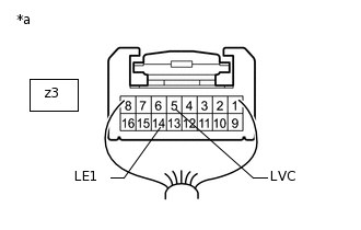
*a
Component with harness connected
(Outer Mirror Control ECU Assembly LH)
Remove the outer mirror control ECU LH with its connectors still connected.
Measure the voltage according to the value(s) in the table below.
Standard Voltage
Tester Connection
Condition
Specified Condition
z3-5 (LVC) - z3-14 (LE1)
Engine switch on (IG)
4.7 to 5.3 V
Measure the resistance according to the value(s) in the table below.
Standard Resistance
Tester Connection
Condition
Specified Condition
z3-14 (LE1) - Body ground
Always
Below 1 Ω
Result
Result
OK
NG
-
CHECK OUTER MIRROR CONTROL ECU ASSEMBLY RH
-
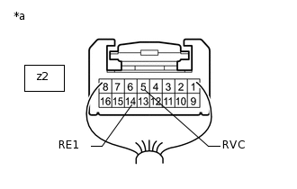
*a
Component with harness connected
(Outer Mirror Control ECU Assembly RH)
Remove the outer mirror control ECU RH with its connectors still connected.
Measure the voltage according to the value(s) in the table below.
Standard Voltage
Tester Connection
Condition
Specified Condition
z2-5 (RVC) - z2-14 (RE1)
Engine switch on (IG)
4.7 to 5.3 V
Measure the resistance according to the value(s) in the table below.
Standard Resistance
Tester Connection
Condition
Specified Condition
z2-14 (RE1) - Body ground
Always
Below 1 Ω
Result
Result
OK
NG
-