FRONT SIDE MEMBER CUT AND JOIN REPLACEMENT SECTIONS (LARGE AREAS)
-
With the front fender front apron assembly removed.
-
REMOVAL
Symbol Meaning 
Remove Weld Points 
Remove Weld Points 
Cut and Join Location 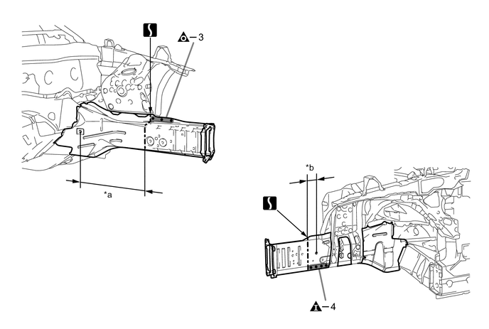
*a 400 mm (15.75 in.) *b 50 mm (1.97 in.)
-
Carefully cut the front side member inner so as not to damage A.
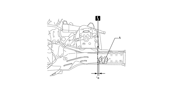
*a 13 mm (0.51 in.) - -
-
-
INSTALLATION
Symbol Meaning 
Plug Weld 
Plug Weld 
Butt Weld
-
Temporarily install the new parts and measure each part of the new parts in accordance with the body dimension diagram. (See the body dimensions)
-
Before temporarily installing the new parts, weld the front side member inner and front side member plate No.4 with the standard number of welding points.
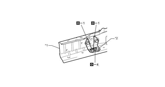
*1 FRONT SIDE MEMBER INNER *2 FRONT SIDE MEMBER PLATE NO.4 -
Make sure to attach correctly in accordance with the body dimension diagram as this part affects the front wheel alignment.
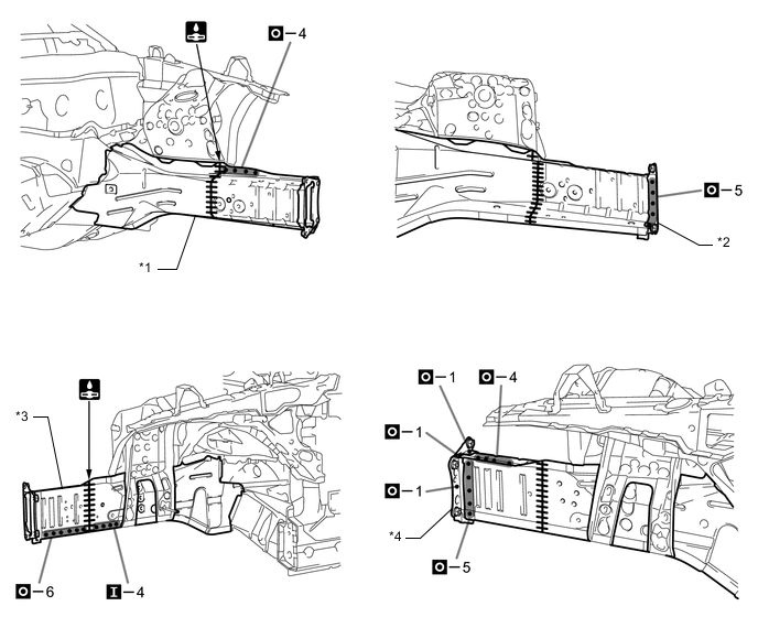
*1 FRONT SIDE MEMBER INNER *2 FRONT BUMPER ARM SUPPORT *3 FRONT SIDE MEMBER PLATE OUTER *4 FRONT SIDE MEMBER REINFORCEMENT NO.1 -
After welding, apply body sealer and undercoating to the corresponding parts. (See the painting /coating)
-
After applying the top coat, apply anti-rust agent to the internal panel portion of the closed section structural weld points.
-