CYLINDER BLOCK REPLACEMENT
PROCEDURE
-
REPLACE STUD BOLT
Note
If a stud bolt is deformed or its threads are damaged, replace it.
-
Using an E5, E7 and E8 "TORX" wrench, remove the stud bolts.
-
Using an E5, E7 and E8 "TORX" wrench, install new stud bolts.
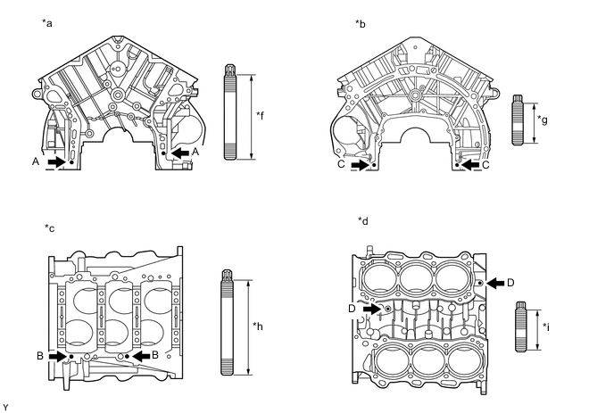
*a Front Side *b Rear Side *c Lower Side *d Upper Side *f 52 mm (2.05 in.) *g 23 mm (0.906 in.) *h 55 mm (2.17 in.) *i 18 mm (0.709 in.) - Torque:
- for stud bolt A and B
- 11 N*m { 112 kgf*cm, 8 ft.*lbf }
- for stud bolt C and D
- 4.0 N*m { 41 kgf*cm, 35 in.*lbf }
-
-
REPLACE STRAIGHT PIN
Note
It is not necessary to remove the straight pin unless it is being replaced.
-
Remove the straight pins.
-
Using a plastic-faced hammer, tap new straight pins into the cylinder block.
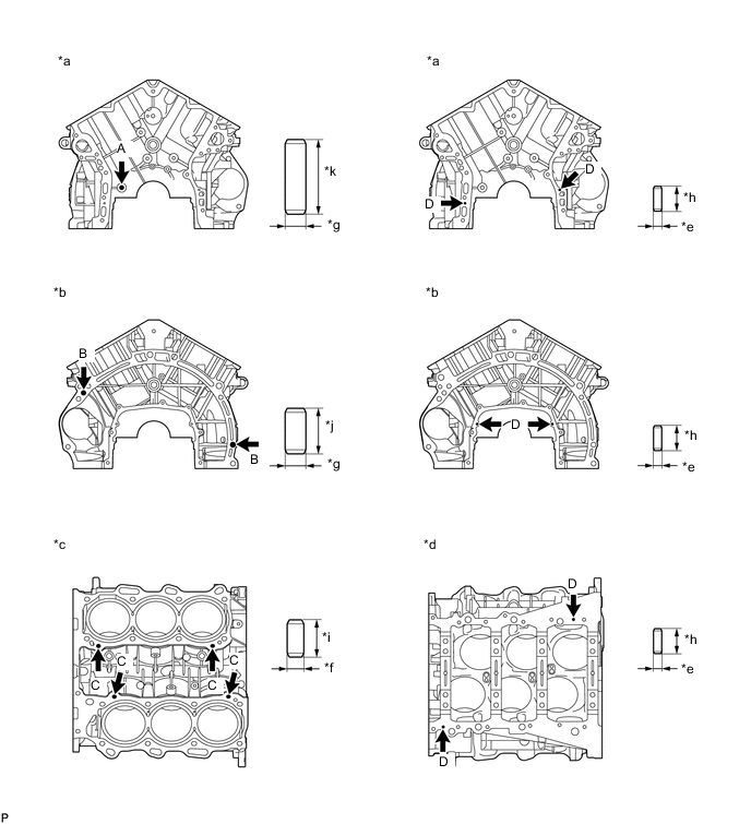
*a Front Side *b Rear Side *c Upper Side *d Lower Side *e 4.0 mm (0.157 in.) *f 8.0 mm (0.315 in.) *g 10 mm (0.394 in.) *h 12 mm (0.472 in.) *i 18 mm (0.709 in.) *j 22 mm (0.866 in.) *k 36 mm (1.42 in.) - - Standard Protrusion Height Item Specified Condition Pin A 22.5 to 23.5 mm (0.886 to 0.925 in.) Pin B 10.5 to 11.5 mm (0.413 to 0.453 in.) Pin C 8.5 to 9.5 mm (0.335 to 0.374 in.) Pin D 5.5 to 6.5 mm (0.217 to 0.256 in.)
-
-
REPLACE OIL JET
Note
It is not necessary to remove the oil jet unless it is being replaced.
-
Using a screwdriver and hammer, tap out the oil jet.
-
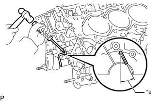
*a 21.5 to 31.5° Using a screwdriver and hammer, tap in a new oil jet as shown in the illustration.
-