VEHICLE STABILITY CONTROL SYSTEM VSC OFF Indicator Light Remains ON
| DTC Code | DTC Name |
|---|---|
| VSC OFF Indicator Light Remains ON |
DESCRIPTION
The skid control ECU is connected to the combination meter via CAN communication.
Pressing the VSC OFF switch turns off traction control and pressing and holding this switch turns off traction and VSC controls. If VSC control turns off, the VSC OFF indicator light comes on.
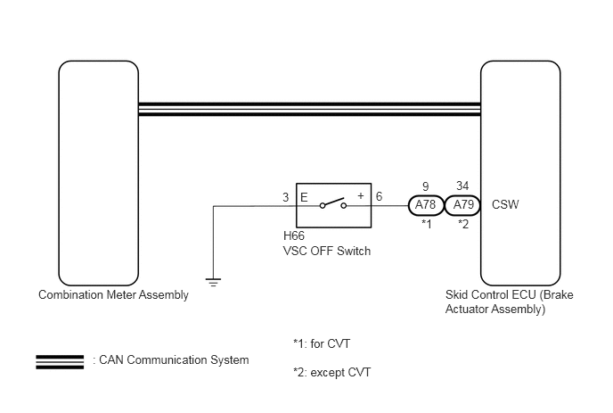
WIRING DIAGRAM
CAUTION / NOTICE / HINT
When replacing the skid control ECU (brake actuator assembly), perform system variant learning and acceleration sensor zero point calibration (Click here).
PROCEDURE
CHECK CAN COMMUNICATION SYSTEM
CHECK IF BRAKE ACTUATOR ASSEMBLY CONNECTOR IS SECURELY CONNECTED
CONNECT CONNECTOR TO BRAKE ACTUATOR ASSEMBLY CORRECTLY
READ VALUE USING GTS (TRC/VSC OFF MODE)
Connect the GTS to the DLC3.
Turn the ignition switch to ON.
Select the Data List on the GTS (Click here).
Table 1. ABS/VSC/TRC Tester Display
Measurement Item/Range
Normal Condition
Diagnostic Note
TRC/VSC Off Mode
TRC/VSC off mode/ Normal, TRC OFF, Unknown or VSC OFF
Normal: Normal mode
TRC OFF: TRC off mode
Unknown: Unspecified
VSC OFF: VSC off mode
-
Check the indicator light and mode condition on the GTS changes according to VSC OFF switch operation.
Standard
Switch Operation
Mode Condition Display
Multi-information Display
(TRC OFF Indicator)
VSC OFF Indicator Light
Not pressed
Normal
Not displayed
Does not come on
Pressing the VSC OFF switch
TRC OFF
Displayed
Does not come on
Pressing and holding the VSC OFF switch
VSC OFF
Displayed
Comes on
Result
Result
Proceed to
Indicator light and mode condition display do not change.
A
Mode condition display is normal, but indicator light does not change.
B
Indicator light and mode condition display are normal.
C
PERFORM ACTIVE TEST USING GTS (VSC OFF INDICATOR LIGHT)
Select the Active Test on the GTS (Click here).
Table 2. ABS/VSC/TRC Tester Display
Test Part
Control Range
Diagnostic Note
VSC OFF Indicator Light
VSC OFF indicator light
Indicator light ON/OFF
Can be observed on the combination meter assembly
Vehicle condition: Vehicle stopped
Check the VSC OFF indicator light in the combination meter assembly turns on or off in accordance with GTS operation.
OK
The VSC OFF indicator light turns on or off in accordance with GTS operation.
INSPECT COMBINATION METER ASSEMBLYClick here
INSPECT VSC OFF SWITCH
Remove the VSC OFF switch (Click here).
Inspect the VSC OFF switch (Click here).
OK
The VSC OFF switch is normal.
CHECK HARNESS AND CONNECTOR (VSC OFF SWITCH - BRAKE ACTUATOR ASSEMBLY AND BODY GROUND)
Disconnect the A78 (for CVT) or A79 (except CVT) skid control ECU (brake actuator assembly) connector.
Measure the resistance according to the value(s) in the table below.
Standard Resistance (for CVT)
Tester Connection
Condition
Specified Condition
A78-9 (CSW) - H66-6 (+)
Always
Below 1 Ω
A78-9 (CSW) or H66-6 (+) - Body ground
Always
10 kΩ or higher
H66-3 (E) - Body ground
Always
Below 1 Ω
Standard Resistance (except CVT)
Tester Connection
Condition
Specified Condition
A79-34 (CSW) - H66-6 (+)
Always
Below 1 Ω
A79-34 (CSW) or H66-6 (+) - Body ground
Always
10 kΩ or higher
H66-3 (E) - Body ground
Always
Below 1 Ω
REPAIR OR REPLACE HARNESS OR CONNECTOR
INSPECT COMBINATION METER ASSEMBLY
Turn the ignition switch off.
Perform an Active Test of the combination meter assembly using the GTS (Click here).
Check the combination meter assembly.
OK
The VSC OFF indicator light turns on or off in accordance with GTS operation.