PARKING SUPPORT ALERT SYSTEM OPERATION CHECK
-
SELF-DIAGNOSIS SYSTEM
-
When a malfunction occurs in the parking support alert system or the system cannot be used, a warning is displayed on the multi-information display, each indicator blinks or is illuminated, and the meter buzzer sounds to inform the driver that the system is unavailable.
Warning Item Multi-information Display Indicator/Meter Buzzer Condition Static objects function malfunction Parking Assist Malfunction
Visit Your Dealer
-
Clearance sonar OFF indicator: Blinks
-
Master warning indicator: Illuminates
-
Meter buzzer: Sounds
Ultrasonic sensor dirty, frozen or open circuit Parking Assist Unavailable
Clean Parking Assist Sensor
-
Clearance sonar OFF indicator: Blinks
-
Master warning indicator: Illuminates
-
Meter buzzer: Sounds
Parking support alert communication malfunction Parking Assist Unavailable
-
Clearance sonar OFF indicator: Blinks
-
Master warning indicator: Illuminates
-
Meter buzzer: Sounds
Rear crossing vehicles function malfunction CHECK RCTA SYSTEM
-
RCTA OFF indicator: Blinks
-
Master warning indicator: Illuminates
-
Meter buzzer: Sounds
Dirt, ice, snow or mud on blind spot monitor sensor RCTA NOT AVAILABLE
-
RCTA OFF indicator: Blinks
-
Master warning indicator: Illuminates
-
Meter buzzer: Sounds
Rear pedestrians function malfunction Rear Camera Detection
Malfunction
Visit Your Dealer
-
RCD OFF indicator: Blinks
-
Master warning indicator: Illuminates
-
Meter buzzer: Sounds
Rear pedestrians function cannot be used temporarily Rear Camera Detection
Unavailable
-
RCD OFF indicator: Blinks
-
Master warning indicator: Illuminates
-
Meter buzzer: Sounds
Dirt on television camera assembly Rear Camera Detection
Unavailable
Remove the Dirt
of Rear Camera
-
RCD OFF indicator: Blinks
-
Master warning indicator: Illuminates
-
Meter buzzer: Sounds
-
-
-
DETECTION RANGE MEASUREMENT AND DISPLAY INSPECTION
Note
Perform the following measurement and inspection with the shift position in a position other than P. Be sure to apply the parking brake and depress the brake pedal firmly to prevent the vehicle from moving.
-
Turn the engine switch on (IG).
-
Turn the static objects function is on.
-
Detection range measurement:
-
Move the shift position according to the table below.
Measurement Area Shift Position Front Corner In any position other than P Front Center In any position other than P or R Rear Corner R Rear Center -
Move a 60 mm (2.4 in.) diameter pole near each sensor to measure its detection range. When measuring the longest-range detection of the front center sensor and the rear center sensor, use a wall or equivalent.
Note
These detection ranges are applicable when positioning the 60 mm (2.4 in.) diameter pole parallel or perpendicular to the ground. The detection range varies depending on the measuring method and type of obstacle (such as walls).
Tech Tips
Have an assistant move the pole.
Figure 1. Corner Sensor Detection Range
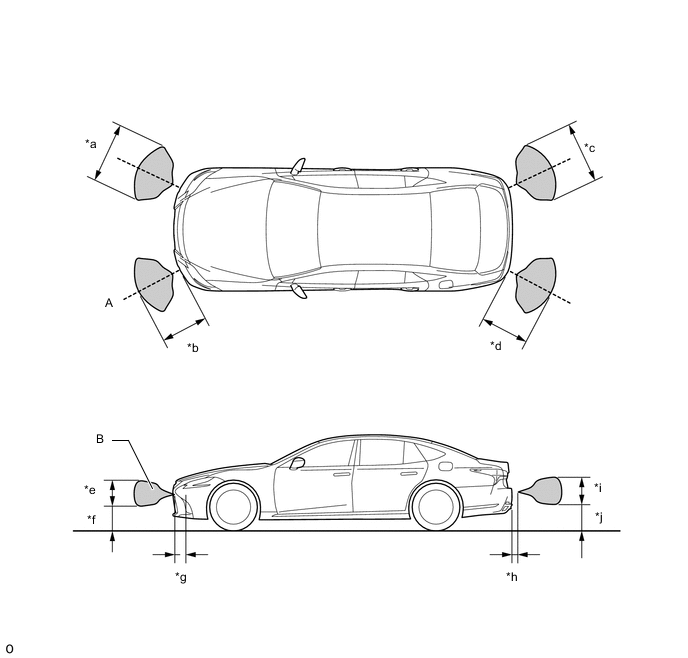
*a Approximately 900mm (35.4 in.) *b Approximately 650mm (25.6 in.) *c Approximately 900mm (35.4 in.) *d Approximately 650mm (25.6 in.) *e Approximately 400mm (15.7 in.) *f Approximately 400mm (15.7 in.) *g Approximately 200mm (7.87 in.) *h Approximately 200mm (7.87 in.) *i Approximately 350mm (13.8 in.) *j Approximately 350mm (13.8 in.) Note
The front corner sensor and rear corner sensor side view detection range (hatched area labeled (B)) represents the cross section of the top view detection range (A). The hatched area (B) does not represent the entire side view detection range.
Figure 2. Front Center Sensor Detection Range
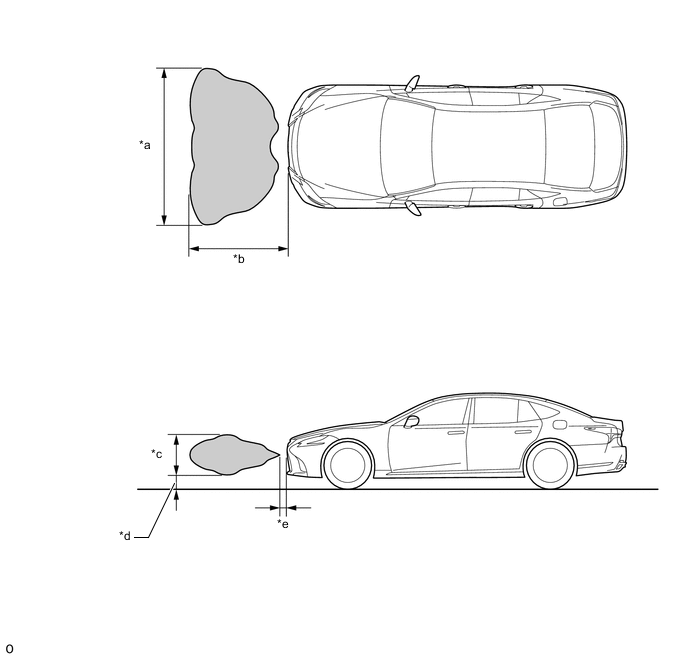
*a Approximately 2000mm (78.7 in.) *b Approximately 1000mm (39.4 in.) *c Approximately 400mm (15.7 in.) *d Approximately 300mm (11.8 in.) *e Approximately 200mm (7.87 in.) - - Figure 3. Rear Center Sensor Detection Range
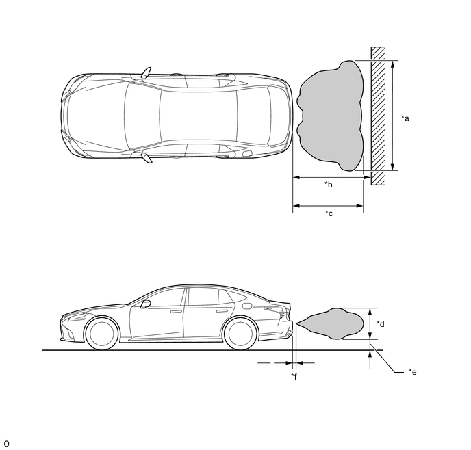
*a Approximately 2000mm (78.7 in.) *b Approximately 1500mm (59.1 in.) *c Approximately 1400mm (55.1 in.) *d Approximately 550mm (21.7 in.) *e Approximately 250mm (9.84 in.) *f Approximately 200mm (7.87 in.)
-
-
Front corner sensor display and buzzer operation check
-
When the Front Corner Ultrasonic Sensor have detected an obstacle, check the displays and check that the buzzer sounds.
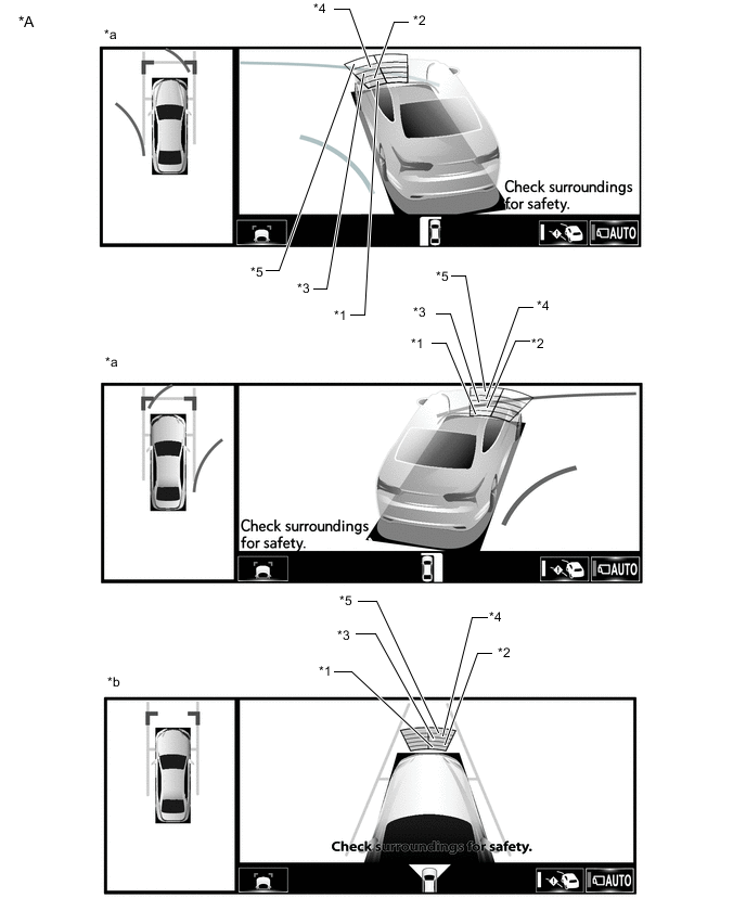
Operation Condition Engine switch Static Objects Function Shift Position Vehicle Speed On (IG) On In any position other than P Less than approximately 10 km/h (6 mph) if speed is increasing Figure 4. Multi-display Icon
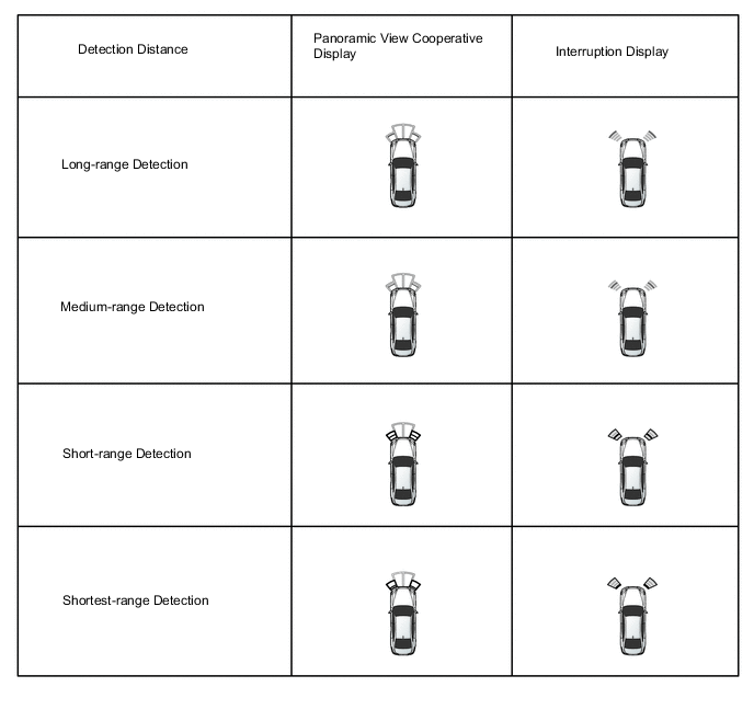
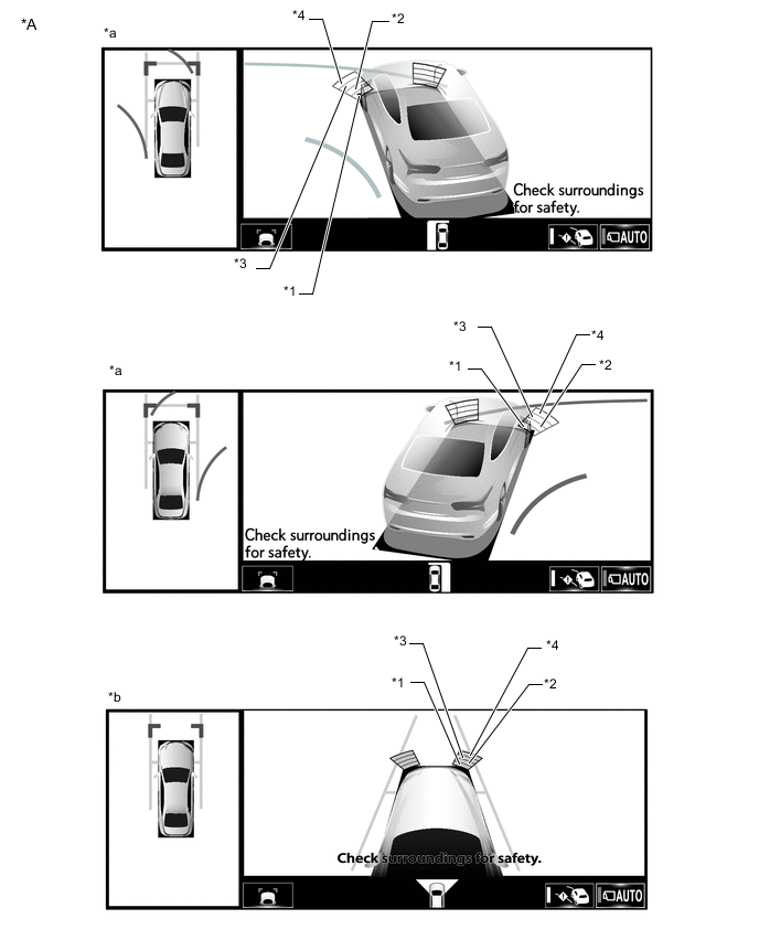
*A Example - - *a Panoramic View and Cornering View Display *b Panoramic View and Side Clearance View Display *1 Closest-range *2 Close-range *3 Medium-range *4 Long-range Figure 5. Headup display (w/ Headup Display System) and Combination Meter Assembly
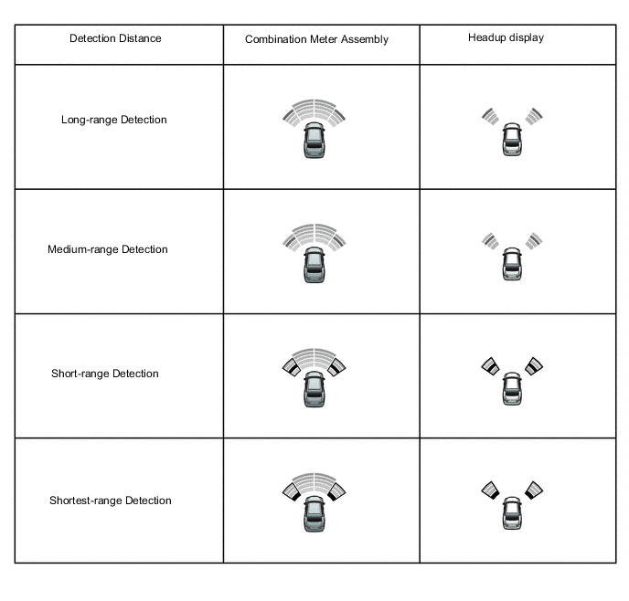
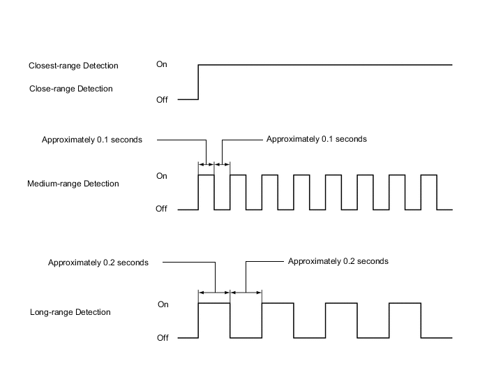
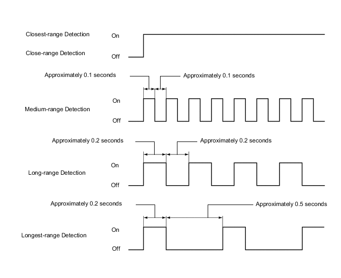
Figure 6. Buzzer Sounding
Tech Tips
Ultrasonic waves are used to measure the detection range; however, the detection range may vary depending on the ambient temperature.
-
-
Front center sensor display and buzzer operation check
-
When the Front Center Ultrasonic Sensor have detected an obstacle, check the display and check that the buzzer sounds.
Operation Condition Engine switch Static Objects Function Shift Position Vehicle Speed On (IG) On In any position other than P or R Less than approximately 10 km/h (6 mph) if speed is increasing Figure 7. Multi-display Icon
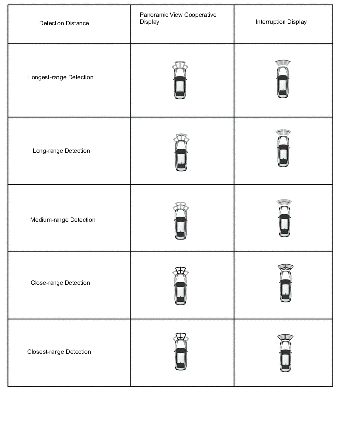
*A Example - - *a Panoramic View and Cornering View Display *b Panoramic View and Side Clearance View Display *1 Closest-range *2 Close-range *3 Medium-range *4 Long-range *5 Longest-range - - Figure 8. Headup display (w/ Headup Display System) and Combination Meter Assembly
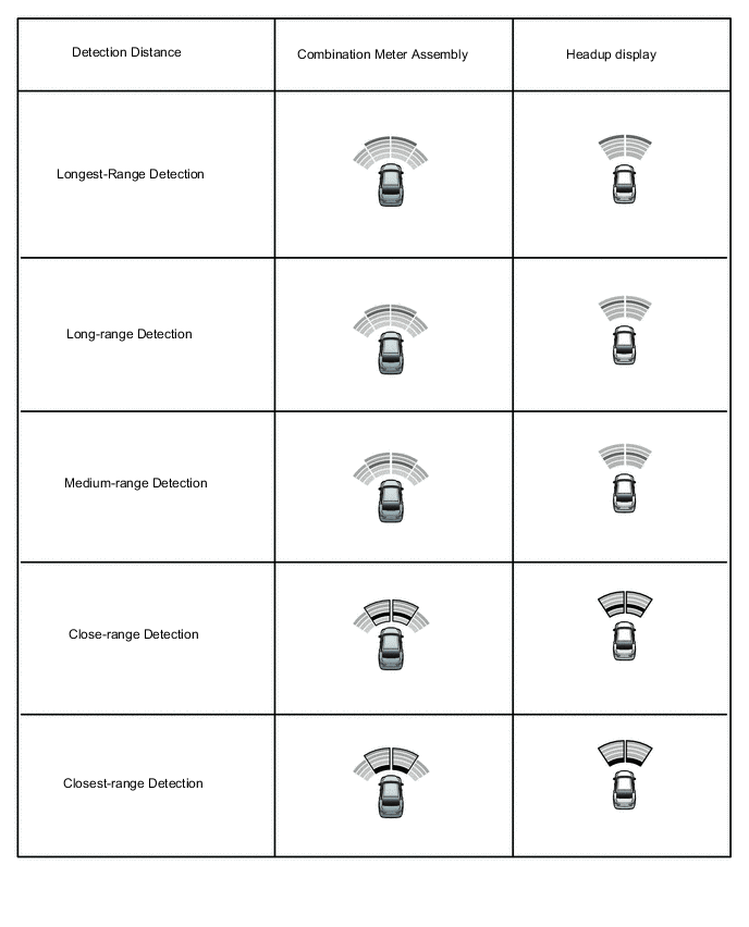
Figure 9. Buzzer Sounding
Tech Tips
Ultrasonic waves are used to measure the detection range; however, the detection range may vary depending on the ambient temperature.
-
-
Rear corner sensor display and buzzer operation check
-
When the Rear Corner Ultrasonic Sensor have detected an obstacle, check the display and check that the buzzer sounds.
Operation Condition Engine switch Static Objects Function Shift Position Vehicle Speed On (IG) On R Less than approximately 10 km/h (6 mph) if speed is increasing Figure 10. Multi-display Icon
Figure 11. Headup display (w/ Headup Display System) and Combination Meter Assembly
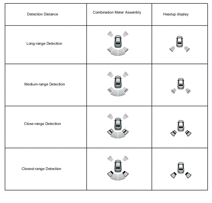
Figure 12. Buzzer Sounding
Tech Tips
Ultrasonic waves are used to measure the detection range; however, the detection range may vary depending on the ambient temperature.
-
-
Rear center sensor display and buzzer operation check
-
When the Rear Center Ultrasonic Sensor have detected an obstacle, check the display and check that the buzzer sounds.
Operation Condition Engine switch Static Objects Function Shift Position Vehicle Speed On (IG) On R Less than approximately 10 km/h (6 mph) if speed is increasing Figure 13. Multi-display Icon
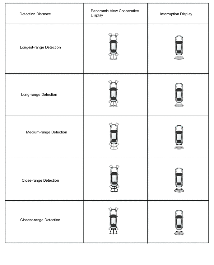
Figure 14. Headup display (w/ Headup Display System) and Combination Meter Assembly
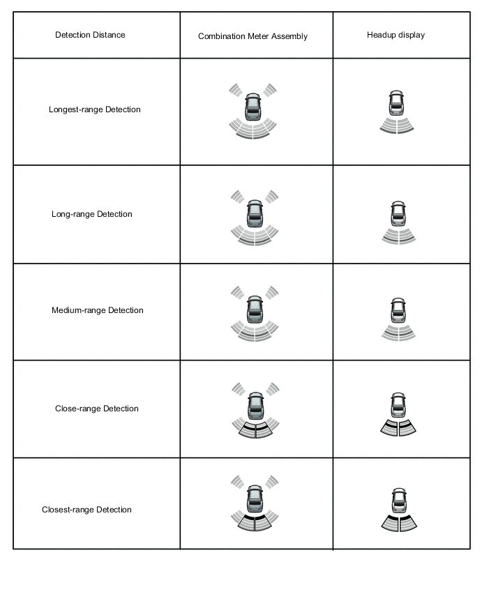
Figure 15. Buzzer Sounding
Tech Tips
Ultrasonic waves are used to measure the detection range; however, the detection range may vary depending on the ambient temperature.
-
-