SFI SYSTEM, Diagnostic DTC:P0693 and P0694
| DTC Code | DTC Name |
|---|---|
| P0693 | Fan 2 Control Circuit Low |
| P0694 | Fan 2 Control Circuit High |
DESCRIPTION
Refer to DTC P0493.
DTC No. |
Detection Item |
DTC Detection Condition |
Trouble Area |
MIL |
Memory |
|---|---|---|---|---|---|
P0693 |
Fan 2 Control Circuit Low |
Open or short in cooling fan control circuit (GMV2 circuit). |
|
Comes on |
DTC stored |
P0694 |
Fan 2 Control Circuit High |
Open or short in cooling fan control circuit (GMV2 circuit). |
|
Comes on |
DTC stored |
MONITOR DESCRIPTION
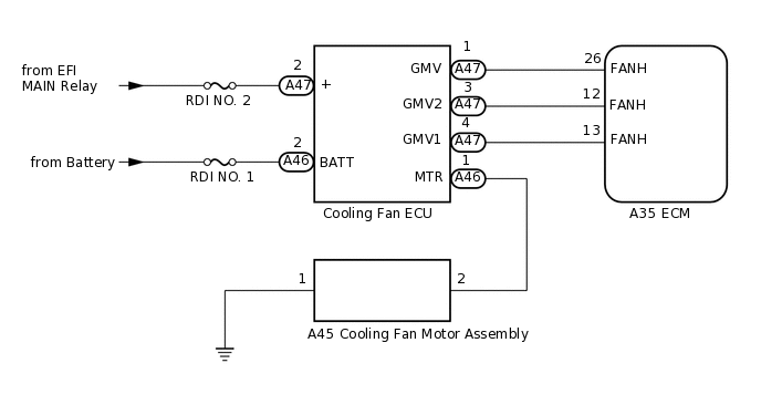
These DTCs are stored when a malfunction is detected in the cooling fan control circuit. If there is an open or short in the cooling fan control circuit, the ECM will illuminate the MIL and store a DTC.
WIRING DIAGRAM
CAUTION / NOTICE / HINT
Inspect the fuses for circuits related to this system before performing the following procedure.
PROCEDURE
CHECK ANY OTHER DTCS OUTPUT (IN ADDITION TO DTC P0693 AND/OR P0694)
Connect the GTS to the DLC3.
Turn the ignition switch to ON.
Turn the GTS on.
Enter the following menus: Powertrain / Engine / Trouble Codes.
Check for DTCs.
Powertrain > Engine > Trouble Codes
Result
Result
Proceed to
DTC P0691 and/or P0692 is output
A
DTC P0691 and/or P0692 and other DTCs are output
B
Tip:If DTC P0691 and/or P0692 and P0562 or P0563 are output simultaneously, troubleshoot for DTC P0562 or P0563 first.
CHECK TERMINAL VOLTAGE (POWER SOURCE OF COOLING FAN ECU)
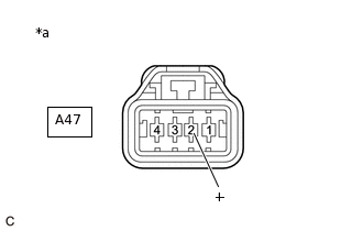
*a
Front view of wire harness connector
(to Cooling Fan ECU)
Disconnect the cooling fan ECU connector.
Turn the ignition switch to ON.
Measure the voltage according to the value(s) in the table below.
Standard Voltage
Tester Connection
Condition
Specified Condition
A47-2 (+) - Body ground
Ignition switch ON
11 to 14 V
Result
Proceed to
OK
NG
NG REPAIR OR REPLACE HARNESS OR CONNECTOR (POWER SOURCE CIRCUIT)
CHECK TERMINAL VOLTAGE (COOLING FAN ECU VOLTAGE)

*a
Front view of wire harness connector
(to Cooling Fan ECU)
Disconnect the cooling fan ECU connector.
Turn the ignition switch to ON.
Measure the voltage according to the value(s) in the table below.
Standard Voltage
Tester Connection
Condition
Specified Condition
A47-3 (GMV2) - Body ground
Ignition switch ON
11 to 14 V
Result
Proceed to
OK
NG
NG CHECK HARNESS AND CONNECTOR (COOLING FAN ECU - ECM)Click here
INSPECT COOLING FAN ECU
Disconnect the cooling fan ECU connector.
Measure the resistance according to the value(s) in the table below.
Standard Resistance
Tester Connection
Condition
Specified Condition
2 (+) - 4 (GMV1)
Always
0.5 to 1.5 Ω
Result
Proceed to
OK
NG
NG REPLACE COOLING FAN ECU
CHECK HARNESS AND CONNECTOR (COOLING FAN ECU - ECM)
Disconnect the cooling fan ECU connector.
Disconnect the ECM connector.
Measure the resistance according to the value(s) in the table below.
Standard Resistance
Tester Connection
Condition
Specified Condition
A47-1 (GMV) - A35-26 (FANH)
Always
Below 1 Ω
A47-4 (GMV1) - A35-13 (FANH)
Always
Below 1 Ω
A47-1 (GMV) or A35-26 (FANH) - Body ground and other terminals
Always
10 kΩ or higher
A47-4 (GMV1) or A35-13 (FANH) - Body ground and other terminals
Always
10 kΩ or higher
Result
Proceed to
OK
NG
NG REPAIR OR REPLACE HARNESS OR CONNECTOR
CHECK HARNESS AND CONNECTOR (COOLING FAN ECU - ECM)
Disconnect the cooling fan ECU connector.
Disconnect the ECM connector.
Measure the resistance according to the value(s) in the table below.
Standard Resistance
Tester Connection
Condition
Specified Condition
A47-3 (GMV2) - A35-12 (FANH)
Always
Below 1 Ω
A47-3 (GMV2) or A35-12 (FANH) - Body ground and other terminals
Always
10 kΩ or higher
Result
Proceed to
OK
NG
NG REPAIR OR REPLACE HARNESS OR CONNECTOR