RELAY ON-VEHICLE INSPECTION
PROCEDURE
INSPECT INTEGRATION RELAY (EFI MAIN)
-
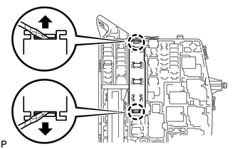
Using a screwdriver, detach the 2 claws, and then disconnect the 3 connectors to remove the integration relay from the engine room junction block.
Tip:Tape the screwdriver tip before use.
-
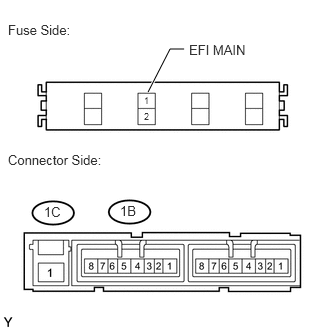
Check the EFI MAIN fuse.
Measure the resistance according to the value(s) in the table below.
Standard Resistance
Tester Connection
Condition
Specified Condition
EFI MAIN fuse
Always
Below 1 Ω
If the result is not as specified, replace the EFI MAIN fuse.
Check the EFI MAIN relay.
Measure the resistance according to the value(s) in the table below.
Standard Resistance
Tester Connection
Condition
Specified Condition
1C-1 - 1B-4
Battery voltage not applied to terminals 1B-2 and 1B-3
10 kΩ or higher
1B-1 - 1B-4
1C-1 - 1B-4
Battery voltage applied to terminals 1B-2 and 1B-3
Below 1 Ω
1B-1 - 1B-4
If the result is not as specified, replace the integration relay.
Install the integration relay.
-
INSPECT INTEGRATION RELAY (IGT/INJ)
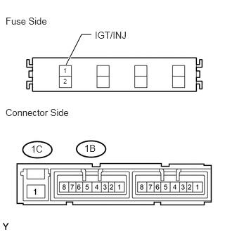
Check the IGT/INJ fuse.
-
Measure the resistance according to the value(s) in the table below.
Standard Resistance
Tester Connection
Condition
Specified Condition
IGT/INJ fuse
Always
Below 1 Ω
If the result is not as specified, replace the IGT/INJ fuse.
-
Check the IGT/INJ relay.
Measure the resistance according to the value(s) in the table below.
Standard Resistance
Tester Connection
Condition
Specified Condition
1C-1 - 1B-8
Battery voltage not applied to terminals 1B-6 and 1B-7
10 kΩ or higher
1B-1 - 1B-8
1C-1 - 1B-8
Battery voltage applied to terminals 1B-6 and 1B-7
Below 1 Ω
1B-1 - 1B-8
If the result is not as specified, replace the integration relay.
INSPECT NO. 1 IGNITION RELAY (IG1)
Note:The circuit opening relay is built into the main body ECU (instrument panel junction block).
Remove the main body ECU (instrument panel junction block).
Measure the resistance according to the value(s) in the table below.
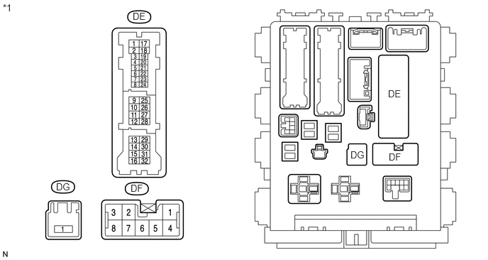
Table 1. Text in Illustration *1
Component without harness connected
(Main body ECU)
Standard Resistance
Tester Connection
Condition
Specified Condition
DF-8 - DG-1
Battery voltage not applied to DF-3 (+) and DE-28 (-)
10 kΩ or higher
DF-8 - DG-1
Battery voltage applied to DF-3 (+) and DE-28 (-)
150 Ω to 200 Ω
If the result is not as specified, replace the main body ECU (instrument panel junction block).
Install the main body ECU (instrument panel junction block).
INSPECT NO. 2 IGNITION RELAY (IG2)
-
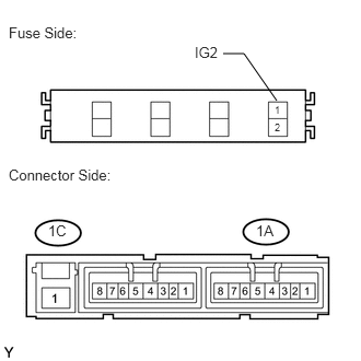
Check the IG2 fuse.
Measure the resistance according to the value(s) in the table below.
Standard Resistance
Tester Connection
Condition
Specified Condition
IG2 fuse
Always
Below 1 Ω
If the result is not as specified, replace the IG2 fuse.
Check the IG2 relay.
Measure the resistance according to the value(s) in the table below.
Standard Resistance
Tester Connection
Condition
Specified Condition
1C-1 - 1A-4
Battery voltage not applied to terminals 1A-2 and 1A-3
10 kΩ or higher
1A-1 - 1A-4
1C-1 - 1A-4
Battery voltage applied to terminals 1A-2 and 1A-3
Below 1 Ω
1A-1 - 1A-4
If the result is not as specified, replace the integration relay.
-
INSPECT CIRCUIT OPENING RELAY (C/OPN)
Note:The circuit opening relay is built into the main body ECU (instrument panel junction block).
Measure the resistance according to the value(s) in the table below.
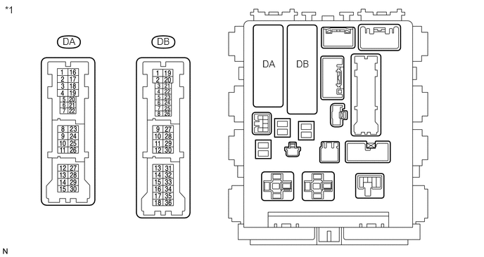
Table 2. Text in Illustration *1
Component without harness connected
(Main body ECU)
Standard Resistance
Tester Connection
Condition
Specified Condition
DA-8 - DB-11
Battery voltage not applied to terminals DB-10 and DB-27
10 kΩ or higher
DA-8 - DB-11
Battery voltage applied to terminals DB-10 and DB-27
Below 1 Ω
If the result is not as specified, replace the main body ECU.