MULTI-MODE MANUAL TRANSAXLE ASSEMBLY INSTALLATION
PROCEDURE
INSTALL MULTI-MODE MANUAL TRANSAXLE ASSEMBLY
-
Check that the 2 knock pins are installed to the engine assembly before installing the multi-mode manual transaxle assembly.
-
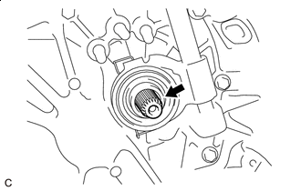

Clutch Spline Grease
Apply clutch spline grease to the input shaft splines.
Grease
Toyota Genuine Clutch Spline Grease or equivalent
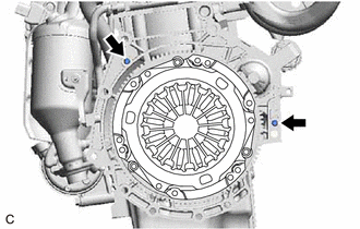
Align the input shaft with the clutch disc and install the multi-mode manual transaxle assembly to the engine assembly.
Install the 4 bolts.
64 N*m
653 kgf*cm
47 ft.*lbf
Note:Make sure that the wire harness or similar items are not pinched between the contact surfaces.
Do not forcibly pry on the multi-mode manual transaxle assembly when installing it to the engine assembly.
Do not apply excessive force to the multi-mode manual transaxle assembly as this will break the input shaft.
Make sure that the 2 knock pins fit securely into the holes when installing the multi-mode manual transaxle assembly to the engine assembly.
Make sure that the contact surfaces of the engine assembly and multi-mode manual transaxle assembly are flat against each other before tightening the bolts.
Be careful not to damage the radiator assembly when installing the multi-mode manual transaxle assembly.
-
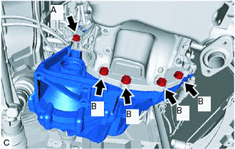
Install the 5 bolts.
Bolt (A)
64 N*m
653 kgf*cm
47 ft.*lbf
Bolt (B)
39 N*m
398 kgf*cm
29 ft.*lbf
-
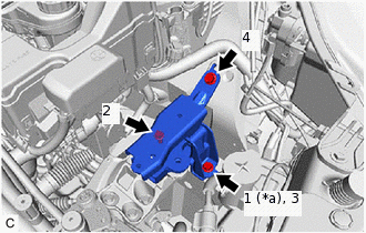
INSTALL ENGINE MOUNTING BRACKET LH
-
*a
Temporarily Install
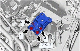
Install the engine mounting bracket LH to the multi-mode manual transaxle assembly with the 4 bolts in the order shown in the illustration.
52 N*m
530 kgf*cm
38 ft.*lbf
-
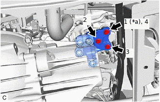
INSTALL ENGINE MOUNTING INSULATOR LH
-
*a
Temporarily Install
Install the engine mounting insulator LH with the 3 bolts in the order shown in the illustration.
52 N*m
530 kgf*cm
38 ft.*lbf
Install the bolt and wire harness clamp bracket.
8.3 N*m
85 kgf*cm
73 in.*lbf
-
*a
Temporarily Install
Install the 3 bolts to the engine mounting bracket LH in the order shown in the illustration.
52 N*m
530 kgf*cm
38 ft.*lbf
-
INSTALL ENGINE MOVING CONTROL ROD BRACKET
-
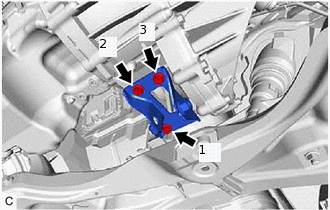
Temporarily install the engine moving control rod bracket to the multi-mode manual transaxle assembly with the 3 bolts.
Fully tighten the 3 bolts in the order shown in the illustration.
52 N*m
530 kgf*cm
38 ft.*lbf
-
INSTALL FAN SHROUD ASSEMBLY
CONNECT NO. 2 RADIATOR HOSE
INSTALL ENGINE MOVING CONTROL ROD
-
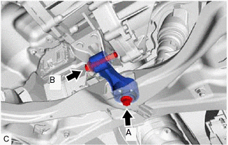
Install the engine moving control rod with the 2 bolts.
Bolt (A)
110 N*m
1122 kgf*cm
81 ft.*lbf
Bolt (B)
120 N*m
1224 kgf*cm
89 ft.*lbf
-
INSTALL FLYWHEEL HOUSING SIDE COVER
INSTALL STARTER ASSEMBLY
INSTALL WIRE HARNESS CLAMP BRACKET
-
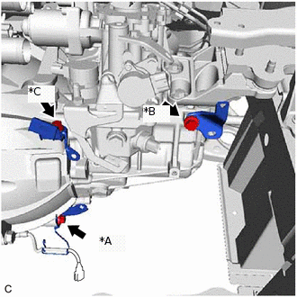
Install the 3 bolts and 3 wire harness clamp brackets to the multi-mode manual transaxle assembly.
Bolt (A)
29.0 N*m
296 kgf*cm
21 ft.*lbf
Bolt (B)
25.5 N*m
260 kgf*cm
19 ft.*lbf
Bolt (C)
12.8 N*m
131 kgf*cm
9 ft.*lbf
-
CONNECT ENGINE WIRE
Connect the 2 shift and select actuator assembly connectors.
Install the wire harness clamp bracket to the shift and select actuator assembly with the bolt.
12.8 N*m
131 kgf*cm
9 ft.*lbf
Engage the 2 clamps to connect the engine wire.
Engage the 4 clamps to connect the engine wire.
Connect the transmission revolution sensor connector.
Connect the back-up light switch assembly connector.
Connect the shift stroke sensor connector.
CONNECT ENGINE ROOM MAIN WIRE
Engage the 3 clamps to connect the engine room main wire.
Connect the park/neutral position switch assembly connector.
Connect the select stroke sensor connector.
CONNECT NO. 3 ENGINE WIRE
Connect the No. 3 engine wire to the multi-mode manual transaxle assembly with the bolt.
12.8 N*m
131 kgf*cm
9 ft.*lbf
Engage the clamp to connect the No. 3 engine wire to the wire harness clamp bracket.
INSTALL CLUTCH ACTUATOR ASSEMBLY
INSTALL AIR CLEANER ASSEMBLY WITH DUCT
INSTALL FRONT DRIVE SHAFT ASSEMBLY
INSTALL FRONT EXHAUST PIPE ASSEMBLY
ADD MANUAL TRANSAXLE OIL
ADD ENGINE COOLANT
INSPECT MANUAL TRANSAXLE OIL
INITIALIZATION AND LEARNING
PERFORM SYNCHRONIZATION POSITION CALIBRATION
INSPECT FOR OIL LEAK
INSPECT FOR EXHAUST GAS LEAK
INSPECT FOR COOLANT LEAK
CONNECT FRONT FENDER LINER LH
Connect the front fender liner LH with the 2 screws and 3 bolts.