LOWER INSTRUMENT PANEL INSTALLATION
CAUTION / NOTICE / HINT
Tech Tips
-
Use the same procedure for RHD and LHD vehicles.
-
The procedure listed below is for LHD vehicles.
-
A bolt without a torque specification is shown in the standard bolt chart.
PROCEDURE
-
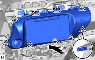
INSTALL LOWER INSTRUMENT PANEL SUB-ASSEMBLY
-
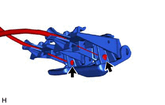
Connect the hood lock control cable and fuel lid lock open cable.
-
Attach the guide and claw to connect the hood lock control lever sub-assembly and fuel lid lock open lever to the lower instrument panel sub-assembly.
-
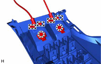
Connect the connector.
-
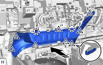
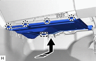
Attach the guide to install the lower instrument panel sub-assembly.
-
Install the 7 screws <B>, 2 bolts <C> and screw <D>.
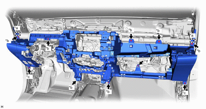
*a Guide *b Screw <B> *c Bolt <C> *d Screw <D>
-
-
INSTALL GLOVE COMPARTMENT DOOR STOPPER SUB-ASSEMBLY
-
Attach the claw to install the glove compartment door stopper sub-assembly.
-
-
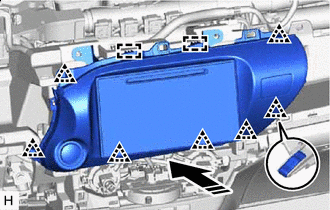
INSTALL LOWER INSTRUMENT COVER SUB-ASSEMBLY
-

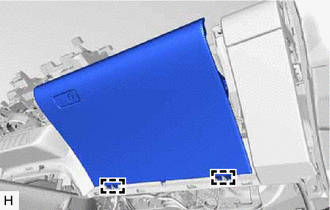
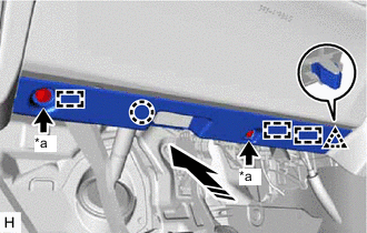
Install in this Direction Connect the connector.
-
Attach the clip and claw to install the lower instrument cover sub-assembly as shown in the illustration.
-
-
INSTALL GLOVE COMPARTMENT DOOR ASSEMBLY
-
Attach the hinge to install the glove compartment door assembly.
-
Attach the claw to connect the glove compartment door stopper sub-assembly.
-
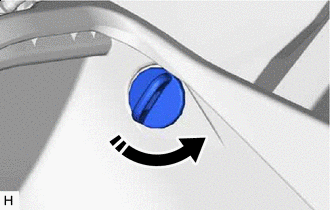
Install in this Direction Install the glove door stopper pin and twist it as shown in the illustration.
Tech Tips
Use the same procedure for both glove door stopper pins.
-
-
INSTALL NO. 2 INSTRUMENT PANEL UNDER COVER SUB-ASSEMBLY
-
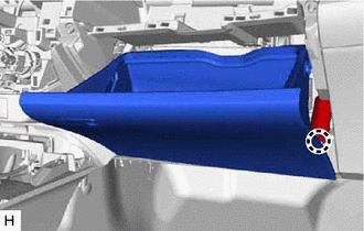
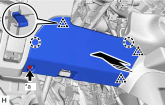
Install in this Direction Attach the guide.
-
Attach the claw to install the No. 2 instrument panel under cover sub-assembly as shown in the illustration.
-
-
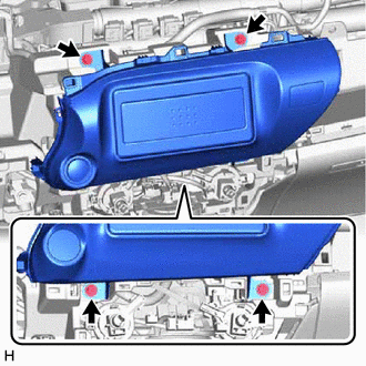
INSTALL LOWER NO. 1 INSTRUMENT PANEL AIRBAG ASSEMBLY (w/ Knee Airbag)
-
INSTALL NO. 1 INSTRUMENT PANEL UNDER COVER SUB-ASSEMBLY (w/ Knee Airbag)
-
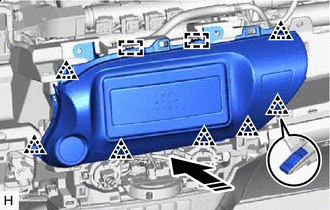
Attach the claw to connect the DLC3.
-
*a Screw <A> Install in this Direction Attach the guide, claw and clip to install the No. 1 instrument panel under cover sub-assembly as shown in the illustration.
-
Install the 2 screws <A>.
-
-
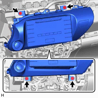
INSTALL LOWER INSTRUMENT PANEL FINISH PANEL SUB-ASSEMBLY (w/o Knee Airbag)
-
Attach the claw to connect the DLC3.
-
*a Screw <A> Install in this Direction Attach the clip and claw to install the lower instrument panel finish panel sub-assembly as shown in the illustration.
-
Install the 2 screws <A>.
-
-
INSTALL CENTER INSTRUMENT CLUSTER FINISH PANEL ASSEMBLY
-
Install in this Direction w/o Audio:
-
Connect the connector.
-
Attach the guide and clip to install the center instrument cluster finish panel assembly as shown in the illustration.
-
Install the 4 screws.
-
-

Install in this Direction w/ Audio, for Radio Receiver Type:
-
Connect the connector.
-
Attach the guide and clip to install the center instrument cluster finish panel assembly as shown in the illustration.
-
Install the 4 screws.
-
-
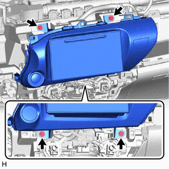
Install in this Direction w/ Audio, for Radio and Display Type:
-
Connect the connector.
-
Attach the guide and clip to install the center instrument cluster finish panel assembly as shown in the illustration.
-

Install the 4 screws.
-
-
Install in this Direction w/ Audio, for Navigation Receiver Type:
-
Connect the connector.
-
Attach the guide and clip to install the center instrument cluster finish panel assembly as shown in the illustration.
-
Install the 4 screws.
-
-
-
INSTALL INTEGRATION PANEL SUB-ASSEMBLY (for Manual Cooler System, for Manual Air Conditioning System)
-
INSTALL CONTROL KNOB SUB-ASSEMBLY (for Manual Cooler System, for Manual Air Conditioning System)
-
INSTALL AIR CONDITIONING CONTROL ASSEMBLY (for Automatic Air Conditioning System)
-
INSTALL HEADLIGHT DIMMER SWITCH ASSEMBLY
-
INSTALL FRONT CONSOLE BOX (w/o Console Box Lid)
-
INSTALL REAR CONSOLE BOX SUB-ASSEMBLY (w/ Rear Console Box)
-
INSTALL CONSOLE BOX ASSEMBLY (w/ Console Box Lid)
-
INSTALL UPPER INSTRUMENT PANEL SUB-ASSEMBLY
-
CONNECT CABLE TO NEGATIVE BATTERY TERMINAL (w/ Airbag System)
Note
When disconnecting the cable, some systems need to be initialized after the cable is reconnected.
-
CHECK SRS WARNING LIGHT (w/ Airbag System)