OIL PUMP REMOVAL
-
DISCHARGE FUEL SYSTEM PRESSURE
CAUTION:
-
Do not disconnect any part of the fuel system until you have discharged the fuel system pressure.
-
Even after discharging the fuel pressure, place a cloth or equivalent over fittings as you separate them to reduce risk of fuel spray on yourself or in the engine compartment.
-
Disconnect the cable from the negative (-) battery terminal.
CAUTION:
Wait at least 90 seconds after disconnecting the cable from the negative (-) battery terminal to prevent airbag and seat belt pretensioner activation.
-
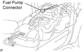
Disconnect the fuel pump connector.
-
Connect the cable to the negative (-) battery terminal.
-
Start the engine. After the engine has stopped on its own, turn the ignition switch OFF.
Tech Tips
DTC P0171/25 (system too lean) may be set.
-
Crank the engine again, then check that the engine does not start.
-
Loosen the fuel tank cap, then discharge the pressure in the fuel tank completely.
-
Connect the fuel pump connector.
-
-
DISCONNECT CABLE FROM NEGATIVE BATTERY TERMINAL
CAUTION:
Wait at least 90 seconds after disconnecting the cable from the negative (-) battery terminal to prevent airbag and seat belt pretensioner activation.
Note
When disconnecting the cable, systems need to be initialized after the cable is reconnected Click here.
-
REMOVE ENGINE ASSEMBLY
-
Remove the engine from the vehicle Click here.
-
-
REMOVE DRIVE PLATE AND RING GEAR ASSEMBLY (for Automatic Transmission)
-
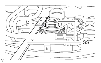
Using SST, hold the crankshaft.
- SST
- 09213-54015 ( 91651-60855 )
- 09330-00021
-
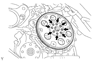
Remove the 8 bolts, rear spacer, drive plate and front spacer.
Note
Do not reuse the bolts.
-
-
REMOVE FLYWHEEL (for Manual Transmission)
-
Using SST, hold the crankshaft.
- SST
- 09213-54015 ( 91651-60855 )
- 09330-00021
-
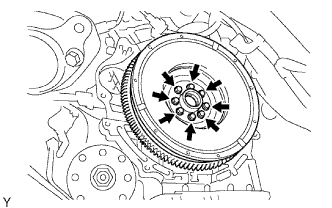
Remove the 8 bolts and flywheel.
Note
Do not reuse the bolts.
-
-
INSTALL ENGINE ASSEMBLY TO STAND
-
REMOVE OIL DIPSTICK GUIDE
-
Remove the oil dipstick gauge.
-
Remove the bolt and oil dipstick guide.
-
Remove the O-ring from the oil dipstick guide.
-
-
REMOVE WATER INLET
-
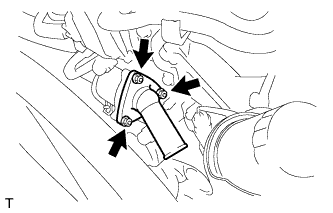
Remove the 3 nuts, water inlet with thermostat and gasket.
-
-
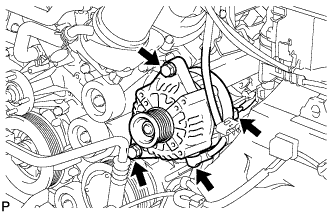
REMOVE GENERATOR
-
Remove the nut and generator wire.
-
Disconnect the generator connector.
-
Remove the 2 bolts and generator.
-
-
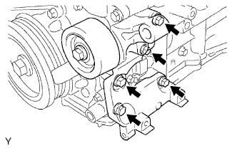
REMOVE V-RIBBED BELT TENSIONER
-
Remove the 5 bolts and V-ribbed belt tensioner.
-
-
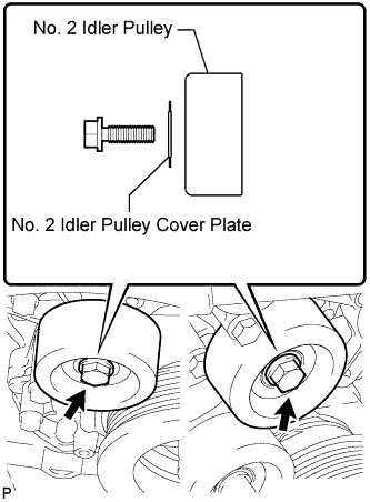
REMOVE NO. 2 IDLER PULLEY
Note
Use the same procedure for both No. 2 idler pulleys.
-
w/ Idler Pulley Cover Plate:
-
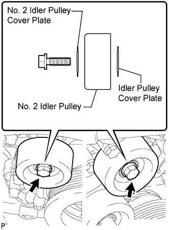
Remove the bolt, No. 2 idler pulley cover plate, idler pulley and idler pulley cover plate.
-
-
w/o Idler Pulley Cover Plate:
-
Remove the bolt, No. 2 idler pulley cover plate and idler pulley.
-
-
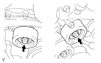
for Integrated Type:
Remove the 2 bolts and 2 No. 2 idler pulleys.
-
-
REMOVE NO. 1 IDLER PULLEY
-
Remove the bolt and idler pulley.
-
-
REMOVE CRANKSHAFT PULLEY
-
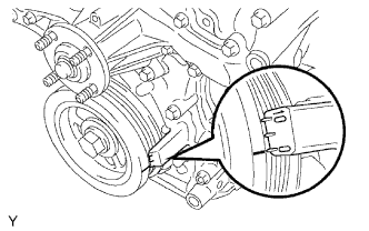
Turn the crankshaft pulley, and align its groove with the timing mark 0 of the timing chain cover.
-
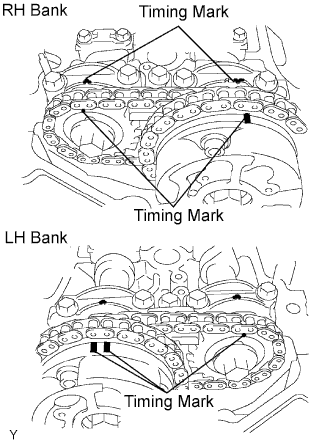
Check that the timing marks of the camshaft timing gears are aligned with the timing marks of the bearing cap as shown in the illustration.
If not, turn the crankshaft 1 revolution (360°) and align the timing marks as above.
-
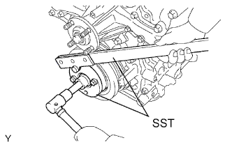
Using SST, hold the crankshaft pulley and loosen the pulley set bolt.
- SST
- 09213-54015 ( 91651-60855 )
- 09330-00021
-
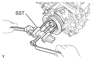
Using the pulley set bolt and SST, remove the crankshaft pulley.
- SST
- 09950-50013 ( 09951-05010, 09952-05010, 09953-05020, 09954-05030 )
-
-
REMOVE NO. 2 OIL PAN
-
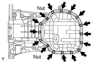
Remove the 14 bolts and 2 nuts.
-
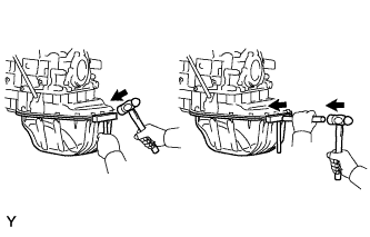
Insert the blade of an oil pan seal cutter between the oil pan and No. 2 oil pan, cut through the applied sealer and remove the No. 2 oil pan.
Note
-
Be careful not to damage the contact surfaces of the oil pan and No. 2 oil pan.
-
Be careful not to damage the No. 2 oil pan flange.
-
-
-
REMOVE OIL STRAINER
-
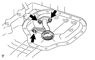
Remove the bolt, 2 nuts, oil strainer and gasket.
-
-
REMOVE NO. 1 OIL PAN
-
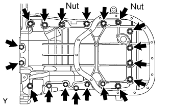
Remove the 17 bolts and 2 nuts.
-
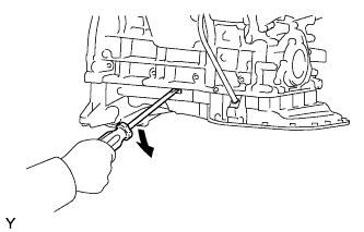
Using a screwdriver, remove the oil pan by prying between the oil pan and cylinder block as shown in the illustration.
Note
Be careful not to damage the contact surfaces of the cylinder block and oil pan.
-
Remove the O-ring from the oil pump.
-
-
REMOVE IGNITION COIL
-
REMOVE CYLINDER HEAD COVER RH
-
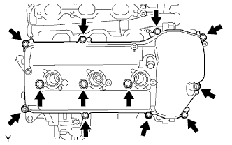
Remove the 10 bolts, 3 seal washers, 2 nuts, head cover and gasket.
-
-
REMOVE CYLINDER HEAD COVER LH
-
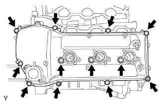
Remove the 10 bolts, 3 seal washers, 2 nuts, cylinder head cover and gasket.
-
Remove the ventilation valve from the cylinder head cover.
-
-
REMOVE CAMSHAFT TIMING OIL CONTROL VALVE
-
Disconnect the 2 oil control valve connectors.
-
Remove the 2 bolts and 2 oil control valves.
-
-
REMOVE VVT SENSOR
-
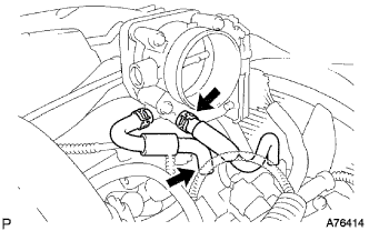
Disconnect the No. 4 and No.5 water by-pass hoses.
-
Disconnect the sensor connector.
-
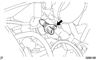
Remove the bolt and sensor.
-
-
REMOVE OIL FILTER BRACKET
-
Remove the 3 bolts, 2 nuts, oil filter bracket and gasket.
-
-
REMOVE TIMING CHAIN COVER
-
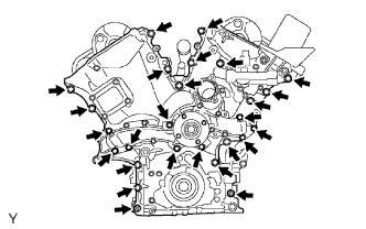
Remove the 24 bolts and 2 nuts.
-
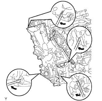
Remove the timing chain cover by prying between the timing chain cover and cylinder head or cylinder block with a screwdriver.
Note
Be careful not to damage the contact surfaces of the timing chain cover, cylinder block and cylinder head.
-
Remove the O-ring from the LH cylinder head.
-
-
REMOVE TIMING CHAIN COVER OIL SEAL
-
Using a screwdriver, pry out the oil seal.
Note
Be careful not to damage the oil pump body. Tape the screwdriver before use..
-