SEAT HEATER SYSTEM Seat Heater for Front Right Seat does not Operate
DESCRIPTION
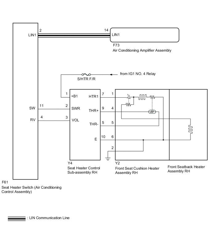
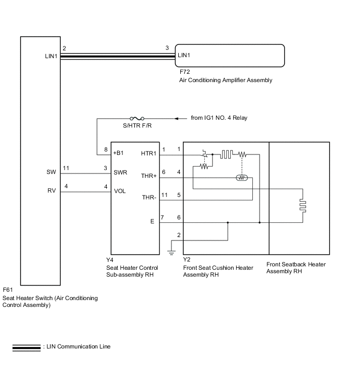
When the seat heater switch on air conditioning control assembly is operated, the seat heater control sub-assembly RH receives the signal. The seat heater control sub-assembly RH receives the signal and operates the front seat heater.
WIRING DIAGRAM
-
for TMC Made
-
for TMMT Made
CAUTION / NOTICE / HINT
Note
-
If the battery voltage is low, the seat heater system may not operate. Refer to Data List for the power steering system.
-
Inspect the fuses for circuits related to this system before performing the following procedure.
PROCEDURE
-
CLEAR DTC
-
Clear the DTCs.
Body Electrical > Air Conditioner > Clear DTCsResult Proceed to NEXT
NEXT 
-
-
CHECK FOR DTC
-
Check for DTCs.
Body Electrical > Air Conditioner > Trouble CodesOK DTC B14B5 is not output. Result Result Proceed to OK (for TMC Made) A OK (for TMMT Made) B NG C
B 
CHECK HARNESS AND CONNECTOR (IG POWER SUPPLY - SEAT HEATER CONTROL SUB-ASSEMBLY RH) Click here
C 
GO TO DIAGNOSTIC TROUBLE CODE CHART Click here
A
-
-
CHECK HARNESS AND CONNECTOR (IG POWER SUPPLY - SEAT HEATER CONTROL SUB-ASSEMBLY RH)
-
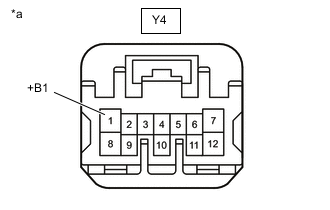
*a Front view of wire harness connector
(to Seat Heater Control Sub-assembly RH)
Disconnect the seat heater control sub-assembly RH connector.
-
Measure the voltage according to the value(s) in the table below.
Standard Voltage Tester Connection Switch Condition Specified Condition Y4-1 (+B1) - Body ground Ignition switch ON 11 to 14 V Ignition switch off Below 1 V Result Proceed to OK NG
NG
REPAIR OR REPLACE HARNESS OR CONNECTOR
OK
-
-
CHECK HARNESS AND CONNECTOR (SEAT HEATER CONTROL SUB-ASSEMBLY RH - FRONT SEAT CUSHION HEATER ASSEMBLY RH - BODY GROUND)
-
Disconnect the Y4 seat heater control sub-assembly RH connector.
-
Disconnect the Y2 front seat cushion heater assembly RH connector.
-
Measure the resistance according to the value(s) in the table below.
Standard Resistance Tester Connection Condition Specified Condition Y4-7 (HTR1) - Y2-1 Always Below 1 Ω Y4-9 (THR+) - Y2-4 Always Below 1 Ω Y4-5 (THR-) - Y2-5 Always Below 1 Ω Y4-10 (E) - Y2-6 Always Below 1 Ω Y2-2 - Body ground Always Below 1 Ω Y4-7 (HTR1) or Y2-1 - Body ground Always 10 kΩ or higher Y4-9 (THR+) or Y2-4 - Body ground Always 10 kΩ or higher Y4-5 (THR-) or Y2-5 - Body ground Always 10 kΩ or higher Y4-10 (E) or Y2-6 - Body ground Always 10 kΩ or higher Result Proceed to OK NG
NG
REPAIR OR REPLACE HARNESS OR CONNECTOR
OK
-
-
INSPECT FRONT SEAT CUSHION HEATER ASSEMBLY RH
-
Remove the front seat cushion heater assembly RH.
-
Inspect the front seat cushion heater assembly RH.
Result Proceed to OK NG
NG
REPLACE FRONT SEAT CUSHION HEATER ASSEMBLY RH Click here
OK
-
-
INSPECT FRONT SEATBACK HEATER ASSEMBLY RH
-
Remove the front seatback heater assembly RH.
-
Inspect the front seatback heater assembly RH.
Result Proceed to OK NG
NG
REPLACE FRONT SEATBACK HEATER ASSEMBLY RH Click here
OK
-
-
CHECK HARNESS AND CONNECTOR (SEAT HEATER SWITCH (AIR CONDITIONING CONTROL ASSEMBLY) - SEAT HEATER CONTROL SUB-ASSEMBLY RH)
-
Disconnect the F61 seat heater switch (air conditioning control assembly) connector.
-
Disconnect the Y4 seat heater control sub-assembly RH connector.
-
Measure the resistance according to the value(s) in the table below.
Standard Resistance Tester Connection Condition Specified Condition F61-11 (SW) - Y4-2 (SWR) Always Below 1 Ω F61-4 (RV) - Y4-3 (VOL) Always Below 1 Ω F61-11 (SW) or Y4-2 (SWR) - Body ground Always 10 kΩ or higher F61-4 (RV) or Y4-3 (VOL) - Body ground Always 10 kΩ or higher Result Proceed to OK NG
NG
REPAIR OR REPLACE HARNESS OR CONNECTOR
OK
-
-
REPLACE SEAT HEATER CONTROL SUB-ASSEMBLY RH
-
Temporarily replace the heater control sub-assembly RH with a new or known good one.
Result Proceed to NEXT
NEXT
-
-
CHECK SEAT HEATER SYSTEM OPERATION
-
Check that the seat heater system is operated normally.
OK The seat heater system is operated normally. Result Proceed to OK NG
OK
END (SEAT HEATER CONTROL SUB-ASSEMBLY WAS DEFECTIVE)
NG
-
-
REPLACE SEAT HEATER SWITCH (AIR CONDITIONING CONTROL ASSEMBLY)
-
Temporarily replace the seat heater switch (air conditioning control assembly) with a new or known good one.
Result Proceed to NEXT
NEXT
-
-
CHECK SEAT HEATER SYSTEM OPERATION
-
Check that the seat heater system is operated normally.
OK The seat heater system is operated normally. Result Proceed to OK NG
OK
END (SEAT HEATER SWITCH (AIR CONDITIONING CONTROL ASSEMBLY) WAS DEFECTIVE)
NG
REPLACE AIR CONDITIONING AMPLIFIER ASSEMBLY Click here
-
-
CHECK HARNESS AND CONNECTOR (IG POWER SUPPLY - SEAT HEATER CONTROL SUB-ASSEMBLY RH)
-
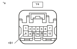
*a Front view of wire harness connector
(to Seat Heater Control Sub-assembly RH)
Disconnect the seat heater control sub-assembly RH connector.
-
Measure the voltage according to the value(s) in the table below.
Standard Voltage Tester Connection Switch Condition Specified Condition Y4-8 (+B1) - Body ground Ignition switch ON 11 to 14 V Ignition switch off Below 1 V Result Proceed to OK NG
NG
REPAIR OR REPLACE HARNESS OR CONNECTOR
OK
-
-
CHECK HARNESS AND CONNECTOR (SEAT HEATER CONTROL SUB-ASSEMBLY RH - FRONT SEAT CUSHION HEATER ASSEMBLY RH - BODY GROUND)
-
Disconnect the Y4 seat heater control sub-assembly RH connector.
-
Disconnect the Y2 front seat cushion heater assembly RH connector.
-
Measure the resistance according to the value(s) in the table below.
Standard Resistance Tester Connection Condition Specified Condition Y4-1 (HTR1) - Y2-1 Always Below 1 Ω Y4-6 (THR+) - Y2-4 Always Below 1 Ω Y4-11 (THR-) - Y2-5 Always Below 1 Ω Y4-7 (E) - Y2-6 Always Below 1 Ω Y2-2 - Body ground Always Below 1 Ω Y4-1 (HTR1) or Y2-1 - Body ground Always 10 kΩ or higher Y4-6 (THR+) or Y2-4 - Body ground Always 10 kΩ or higher Y4-11 (THR-) or Y2-5 - Body ground Always 10 kΩ or higher Y4-7 (E) or Y2-6 - Body ground Always 10 kΩ or higher Result Proceed to OK NG
NG
REPAIR OR REPLACE HARNESS OR CONNECTOR
OK
-
-
INSPECT FRONT SEAT CUSHION HEATER ASSEMBLY RH
-
Remove the front seat cushion heater assembly RH.
-
Inspect the front seat cushion heater assembly RH.
Result Proceed to OK NG
NG
REPLACE FRONT SEAT CUSHION HEATER ASSEMBLY RH Click here
OK
-
-
INSPECT FRONT SEATBACK HEATER ASSEMBLY RH
-
Remove the front seatback heater assembly RH.
-
Inspect the front seatback heater assembly RH.
Result Proceed to OK NG
NG
REPLACE FRONT SEATBACK HEATER ASSEMBLY RH Click here
OK
-
-
CHECK HARNESS AND CONNECTOR (SEAT HEATER SWITCH (AIR CONDITIONING CONTROL ASSEMBLY) - SEAT HEATER CONTROL SUB-ASSEMBLY RH)
-
Disconnect the F61 seat heater switch (air conditioning control assembly) connector.
-
Disconnect the Y4 seat heater control sub-assembly RH connector.
-
Measure the resistance according to the value(s) in the table below.
Standard Resistance Tester Connection Condition Specified Condition F61-11 (SW) - Y4-3 (SWR) Always Below 1 Ω F61-4 (RV) - Y4-4 (VOL) Always Below 1 Ω F61-11 (SW) or Y4-3 (SWR) - Body ground Always 10 kΩ or higher F61-4 (RV) or Y4-4 (VOL) - Body ground Always 10 kΩ or higher Result Proceed to OK NG
NG
REPAIR OR REPLACE HARNESS OR CONNECTOR
OK
-
-
REPLACE SEAT HEATER CONTROL SUB-ASSEMBLY RH
-
Temporarily replace the heater control sub-assembly RH with a new or known good one.
Result Proceed to NEXT
NEXT
-
-
CHECK SEAT HEATER SYSTEM OPERATION
-
Check that the seat heater system is operated normally.
OK The seat heater system is operated normally. Result Proceed to OK NG
OK
END (SEAT HEATER CONTROL SUB-ASSEMBLY WAS DEFECTIVE)
NG
-
-
REPLACE SEAT HEATER SWITCH (AIR CONDITIONING CONTROL ASSEMBLY)
-
Temporarily replace the seat heater switch (air conditioning control assembly) with a new or known good one.
Result Proceed to NEXT
NEXT
-
-
CHECK SEAT HEATER SYSTEM OPERATION
-
Check that the seat heater system is operated normally.
OK The seat heater system is operated normally. Result Proceed to OK NG
OK
END (SEAT HEATER SWITCH (AIR CONDITIONING CONTROL ASSEMBLY) WAS DEFECTIVE)
NG
REPLACE AIR CONDITIONING AMPLIFIER ASSEMBLY Click here
-