DYNAMIC RADAR CRUISE CONTROL SYSTEM Clutch Switch Circuit
| DTC Code | DTC Name |
|---|---|
| Clutch Switch Circuit |
DESCRIPTION
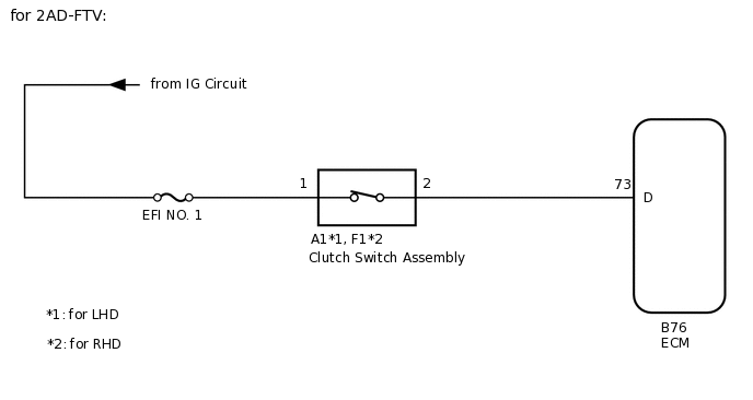
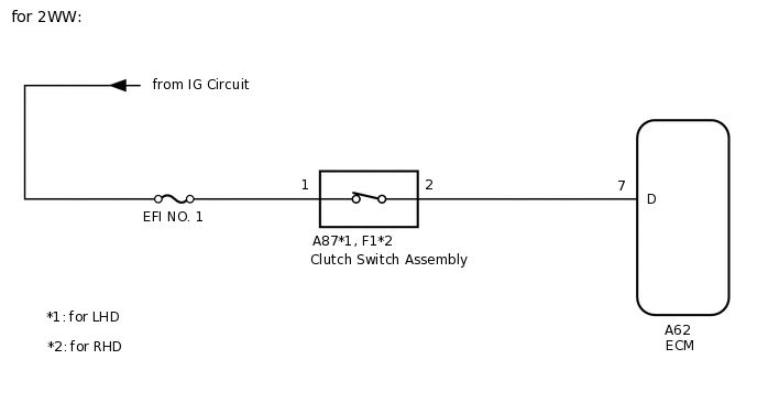
While depressing the clutch pedal, the clutch switch sends a signal to terminal D of the ECM. The ECM cancels cruise control when terminal D receives the signal.
WIRING DIAGRAM


CAUTION / NOTICE / HINT
Inspect the fuses for circuits related to this system before performing the following inspection procedure.
PROCEDURE
INSPECT CLUTCH SWITCH ASSEMBLY
Remove the clutch switch assembly.
Inspect the clutch switch assembly.
Result
Proceed to
OK
NG
CHECK HARNESS AND CONNECTOR (CLUTCH SWITCH ASSEMBLY - ECM AND BATTERY)
for 2AD-FTV
Disconnect the A1*1 or F1*2 clutch switch assembly connector.
*1: for LHD
*2: for RHD
Disconnect the B76 ECM connector.
Measure the resistance according to the value(s) in the table below.
Standard Resistance
Table 1. for LHD Tester Connection
Condition
Specified Condition
A1-2 - B76-73 (D)
Always
Below 1 Ω
A1-2 or B76-73 (D) - Body ground
Always
10 kΩ or higher
Table 2. for RHD Tester Connection
Condition
Specified Condition
F1-2 - B76-73 (D)
Always
Below 1 Ω
F1-2 or B76-73 (D) - Body ground
Always
10 kΩ or higher
Measure the voltage according to the value(s) in the table below.
Standard Voltage
Table 3. for LHD Tester Connection
Switch Condition
Specified Condition
A1-1 - Body ground
Ignition switch ON
11 to 14 V
A1-1 - Body ground
Ignition switch off
Below 1 V
Table 4. for RHD Tester Connection
Switch Condition
Specified Condition
F1-1 - Body ground
Ignition switch ON
11 to 14 V
F1-1 - Body ground
Ignition switch off
Below 1 V
for 2AR-FE
Disconnect the A1*1 or F1*2 clutch switch assembly connector.
*1: for LHD
*2: for RHD
Disconnect the B77 ECM connector.
Measure the resistance according to the value(s) in the table below.
Standard Resistance
Table 5. for LHD Tester Connection
Condition
Specified Condition
A1-2 - B77-67 (D)
Always
Below 1 Ω
A1-2 or B77-67 (D) - Body ground
Always
10 kΩ or higher
Table 6. for RHD Tester Connection
Condition
Specified Condition
F1-2 - B77-67 (D)
Always
Below 1 Ω
F1-2 or B77-67 (D) - Body ground
Always
10 kΩ or higher
Measure the voltage according to the value(s) in the table below.
Standard Voltage
Table 7. for LHD Tester Connection
Switch Condition
Specified Condition
A1-1 - Body ground
Ignition switch ON
11 to 14 V
A1-1 - Body ground
Ignition switch off
Below 1 V
Table 8. for RHD Tester Connection
Switch Condition
Specified Condition
F1-1 - Body ground
Ignition switch ON
11 to 14 V
F1-1 - Body ground
Ignition switch off
Below 1 V
for 3ZR-FE
Disconnect the A1*1 or F1*2 clutch switch assembly connector.
*1: for LHD
*2: for RHD
Disconnect the B75 ECM connector.
Measure the resistance according to the value(s) in the table below.
Standard Resistance
Table 9. for LHD Tester Connection
Condition
Specified Condition
A1-2 - B75-81 (D)
Always
Below 1 Ω
A1-2 or B75-81 (D) - Body ground
Always
10 kΩ or higher
Table 10. for RHD Tester Connection
Condition
Specified Condition
F1-2 - B75-81 (D)
Always
Below 1 Ω
F1-2 or B75-81 (D) - Body ground
Always
10 kΩ or higher
Measure the voltage according to the value(s) in the table below.
Standard Voltage
Table 11. for LHD Tester Connection
Switch Condition
Specified Condition
A1-1 - Body ground
Ignition switch ON
11 to 14 V
A1-1 - Body ground
Ignition switch off
Below 1 V
Table 12. for RHD Tester Connection
Switch Condition
Specified Condition
F1-1 - Body ground
Ignition switch ON
11 to 14 V
F1-1 - Body ground
Ignition switch off
Below 1 V
for 3ZR-FAE
Disconnect the A1*1 or F1*2 clutch switch assembly connector.
*1: for LHD
*2: for RHD
Disconnect the B93 ECM connector.
Measure the resistance according to the value(s) in the table below.
Standard Resistance
Table 13. for LHD Tester Connection
Condition
Specified Condition
A1-2 - B93-65 (D)
Always
Below 1 Ω
A1-2 or B93-65 (D) - Body ground
Always
10 kΩ or higher
Table 14. for RHD Tester Connection
Condition
Specified Condition
F1-2 - B93-65 (D)
Always
Below 1 Ω
F1-2 or B93-65 (D) - Body ground
Always
10 kΩ or higher
Measure the voltage according to the value(s) in the table below.
Standard Voltage
Table 15. for LHD Tester Connection
Switch Condition
Specified Condition
A1-1 - Body ground
Ignition switch ON
11 to 14 V
A1-1 - Body ground
Ignition switch off
Below 1 V
Table 16. for RHD Tester Connection
Switch Condition
Specified Condition
F1-1 - Body ground
Ignition switch ON
11 to 14 V
F1-1 - Body ground
Ignition switch off
Below 1 V
for 2WW
Disconnect the A87*1 or F1*2 clutch switch assembly connector.
*1: for LHD
*2: for RHD
Disconnect the A62 ECM connector.
Measure the resistance according to the value(s) in the table below.
Standard Resistance
Table 17. for LHD Tester Connection
Condition
Specified Condition
A87-2 - A62-7 (D)
Always
Below 1 Ω
A87-2 or A62-7 (D) - Body ground
Always
10 kΩ or higher
Table 18. for RHD Tester Connection
Condition
Specified Condition
F1-2 - A62-7 (D)
Always
Below 1 Ω
F1-2 or A62-7 (D) - Body ground
Always
10 kΩ or higher
Measure the voltage according to the value(s) in the table below.
Standard Voltage
Table 19. for LHD Tester Connection
Switch Condition
Specified Condition
A87-1 - Body ground
Ignition switch ON
11 to 14 V
A87-1 - Body ground
Ignition switch off
Below 1 V
Table 20. for RHD Tester Connection
Switch Condition
Specified Condition
F1-1 - Body ground
Ignition switch ON
11 to 14 V
F1-1 - Body ground
Ignition switch off
Below 1 V
Result
Proceed to
OK
NG
OK REPLACE ECM
for 2AD-FTV:Click here
for 2AR-FE:Click here
for 3ZR-FAE:Click here
for 3ZR-FE:Click here
for 2WW:Click here
NG REPAIR OR REPLACE HARNESS OR CONNECTOR