ECD SYSTEM(for CCo) SYSTEM DESCRIPTION
ENGINE CONTROL SYSTEM
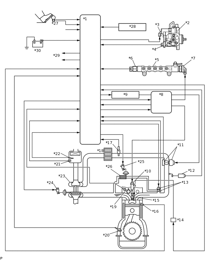
*1
ECM
*2
Fuel Supply Pump
*3
Suction Control Valve
*4
Fuel Temperature Sensor
*5
Common Rail
*6
Fuel Pressure Sensor
*7
Pressure Discharge Valve
*8
Injector Driver (EDU)
*9
EDU Relay
*10
Injector
*11
Diesel Throttle Body Assembly
*12
Manifold Absolute Pressure Sensor
*13
EGR Valve Assembly
*14
GLOW Relay
*15
Glow Plug
*16
Engine Coolant Temperature Sensor
*17
Intake Air Temperature Sensor (Turbo)
*18
Intercooler
*19
Camshaft Position Sensor
*20
Crankshaft Position Sensor
*21
Mass Air Flow Meter Assembly
*22
Intake Air Temperature Sensor (built into Mass Air Flow Meter Assembly)
*23
Turbocharger
*24
Vacuum Regulating Valve Assembly (for Turbocharger Control)
*25
Vacuum Switching Valve Assembly (for EGR Cooler)
*26
EGR Cooler
*27
Accelerator Pedal Position Sensor
*28
Generator
*29
Cooling Fan Relay
*30
Battery
COMMON RAIL SYSTEM DESCRIPTION
Common rail system:
The common rail system uses high-pressurized fuel for improved fuel economy. This system also provides robust engine power, while suppressing engine vibration and noise.
This system stores fuel in the common rail, which has been pressurized and supplied by the supply pump. By storing fuel at high-pressure, the common rail system can provide fuel at stable fuel injection pressures, regardless of engine speed or engine load.
The ECM, using the EDU, provides an electric current to the piezo actuator in each injector to regulate the fuel injection timing and volume. The ECM also monitors the internal fuel pressure of the common rail using the fuel pressure sensor. The ECM causes the supply pump to supply the fuel necessary to obtain the target fuel pressure.
In addition, this system uses a piezo actuator inside each injector to open and close the fuel passages. Therefore, both fuel injection time and fuel injection volume can be precisely regulated by the ECM.
The common rail system allows a two stage fuel injection process. In order to soften combustion shock, this system performs "pilot-injection" prior to the main fuel injection. This helps to reduce engine vibration and noise.
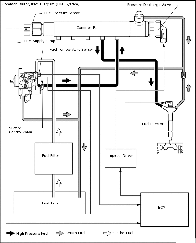
Common rail system components:
Component
Description
Common rail
Stores high-pressure fuel produced by supply pump
Supply pump
Operated by crankshaft
Supplies high-pressure fuel to common rail
Injector
Injects fuel to combustion chamber based on signals from ECM
Fuel pressure sensor
Monitors internal fuel pressure of common rail and sends signals to ECM
Pressure Discharge Valve
Based on signals from the ECM, opens valve when sudden deceleration is occurred, or when the ignition switch is OFF to prevent the fuel pressure from becoming too high.
Suction control valve
Based on signals from ECM, adjusts fuel volume supplied to common rail and regulates internal fuel pressure
Check valve
Keeps pressure that discharges from injector
Diagnostic trouble codes (DTCs) table for the common rail system
Tip:This table indicates typical DTC combinations for each malfunction occurrence.
Trouble Area
Malfunction
DTC No.
Injector
Open or short in injector circuit
P0093*, P0201, P0202, P0203, P0204, P062D
Stuck open
P0093
Stuck closed
P0301, P0302, P0303, P0304
Fuel pressure sensor
Open or short in fuel pressure sensor circuit or pressure sensor output fixed
P0087, P0190, P0191, P0192, P0193
Pressure discharge valve
Open or short in pressure discharge valve circuit
P0088*, P0093*, P1229*, P1271, P1272
Stuck open
P0093
Stuck closed
P0088*, P1272
Suction control valve
Open or short in suction control valve circuit
P0088*, P0627, P1229
Stuck open
P0088*, P1229
EDU
Faulty EDU
P0093*, P0201*, P0202*, P0203*, P0204*, P062D*, P1271*, P1272*
Common rail system (Fuel system)
Fuel leaks in high-pressure area
P0093
*: There may be no DTC output depending on the condition of the malfunction.
Diagnostic trouble code description for the common rail system:
DTC No.
Description
P0087
Fuel pressure sensor output does not change
P0088
Internal fuel pressure too high (220000 kPa [2243.4 kgf/cm2, 31900 psi] or more)
P0093
Fuel leaks in high-pressure areas
P0190
Open or short in fuel pressure sensor circuit (output voltage is too low or too high)
P0192
Open or short in fuel pressure sensor circuit (output voltage is too low)
P0193
Open or short in fuel pressure sensor circuit (output voltage is too high)
P0201
Open or short in No. 1 injector circuit
P0202
Open or short in No. 2 injector circuit
P0203
Open or short in No. 3 injector circuit
P0204
Open or short in No. 4 injector circuit
P0301
Cylinder 1 misfire detected
P0302
Cylinder 2 misfire detected
P0303
Cylinder 3 misfire detected
P0304
Cylinder 4 misfire detected
P0627
Open or short in suction control valve circuit
P062D
Open or short in injector driver or injector circuit
P1229
Fuel over-feed
P1271
Open or short in pressure discharge valve circuit
P1272
Pressure discharge valve stuck close
INJECTION CONTROL SYSTEM DESCRIPTION
The ECM controls the fuel injection system through the EDU, injectors, and supply pump.
The ECM determines the injection volume and injection timing based on signals from the acceleration position sensor, crank position sensor, and camshaft position sensor. Based on the signals from the ECM, the EDU controls the injectors. The EDU also controls the suction control valve installed on the supply pump to help regulate fuel pressure.
The Piezo type injector used in the 2AD-FTV engine makes noise when the engine is idling because this injector operates at high speed. Therefore, the EDU controls the injector to operate at low speed when the engine is idling based on signals from the ECM to achieve noise reduction.
The feed pump is used to pump fuel from the fuel tank to the supply pump.
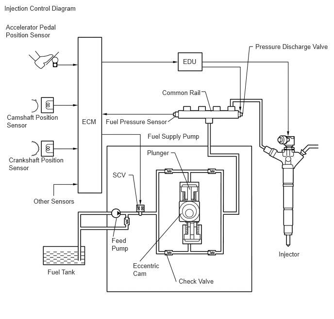
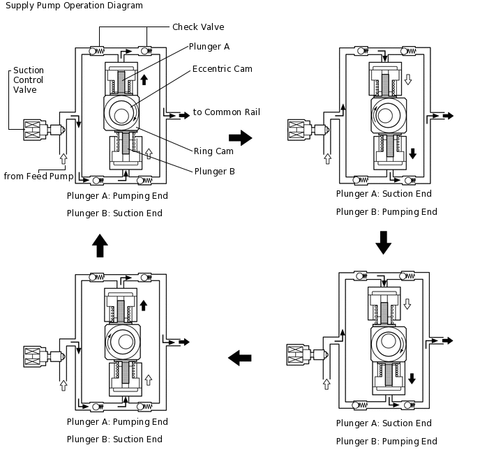
SUPPLY PUMP OPERATION SYSTEM DESCRIPTION
The rotation of the eccentric cam in the supply pump causes the ring cam in the supply pump to push plunger A upward as illustrated below. The spring force pulls plunger B (located opposite to plunger A) upward. As a result, plunger B draws the fuel in, and plunger A pumps fuel out at the same time.
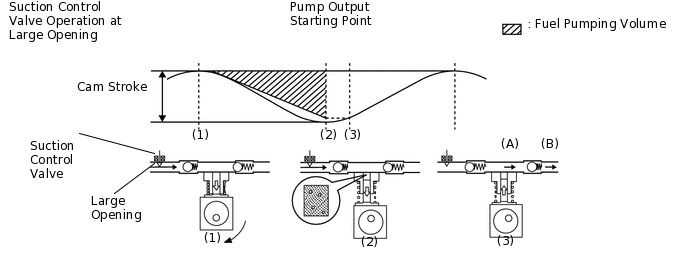
SUCTION CONTROL VALVE OPERATION SYSTEM DESCRIPTION
Tip:The ECM controls the suction control valve operation to regulate the fuel volume that is produced by the supply pump for the common rail. This control is performed to regulate the internal fuel pressure of the common rail to the targeted injection pressure.
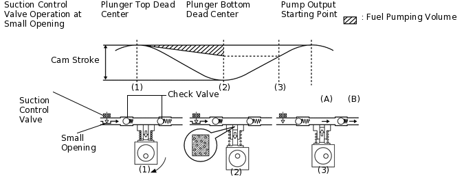
Small opening of the suction control valve:
When the opening of the suction control valve is small, the volume of supplied fuel is small.
The suction volume becomes small due to the narrow path despite the plunger stroke being full. The difference between the geometrical volume and suction volume creates a vacuum.
Pump output will start when the fuel pressure at (A) becomes higher than the common rail pressure (B).
Large opening of the suction control valve:
When the opening of the suction control valve is large, the volume of supplied fuel is increased.
If the plunger stroke is full, the suction volume becomes large because of the wide path.
Pump output will start when the fuel pressure at (A) becomes higher than the common rail pressure (B).