BLACK OUT TAPE(for Rear Door) INSTALLATION
PROCEDURE
-
PRECAUTION
Note
After turning the power switch off, waiting time may be required before disconnecting the cable from the negative (-) auxiliary battery terminal. Therefore, make sure to read the disconnecting the cable from the negative (-) auxiliary battery terminal notices before proceeding with work Click here.
-
REPAIR INSTRUCTION
-
INSTALL NO. 2 BLACK OUT TAPE
-
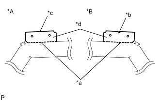
Text in Illustration *A LH Side *B RH Side *a Perforation *b Triangle *c Straight Line *d Remove Remove the portion of the No. 2 black out tape at the perforation as shown in the illustration.
-
Refer to the illustration to position the No. 2 black out tape.
Standard Measurement Dimension Measurement A 2.0 to 4.0 mm (0.0787 to 0.157 in.) B 4.0 to 6.0 mm (0.157 to 0.236 in.) -
Remove the release paper and apply the tape.
-
-
INSTALL REAR DOOR LOWER OUTSIDE STRIPE
-
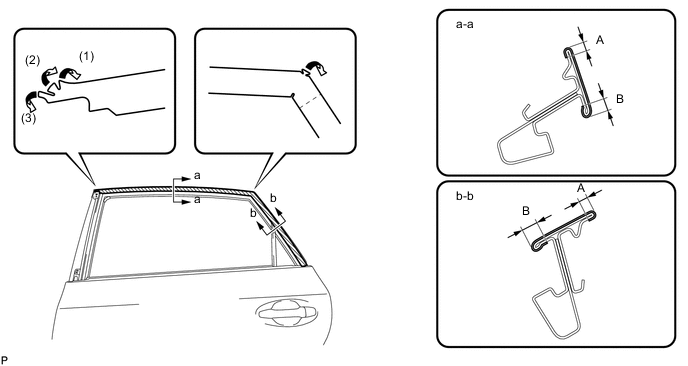
Refer to the illustration to position the rear door lower outside stripe.
Text in Illustration *A LH Side *B RH Side *a Triangle *b Edge of Curved Surface *c Straight Line - - Standard Measurement Dimension Measurement A 2.0 mm (0.0787 in.) -
Remove the release paper and apply the stripe.
-
-
INSTALL REAR DOOR UPPER OUTSIDE STRIPE
-
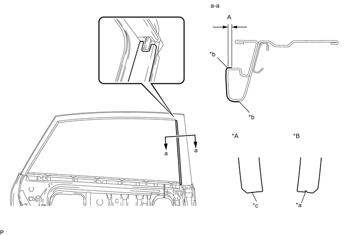
Refer to the illustration to position the rear door upper outside stripe.
Text in Illustration *A LH Side *B RH Side *a Triangle *b Edge of Curved Surface *c Straight Line - - Standard Measurement Dimension Measurement A 2.0 mm (0.0787 in.) -
Remove the release paper and apply the stripe.
-
-
INSTALL REAR DOOR OUTSIDE STRIPE
-
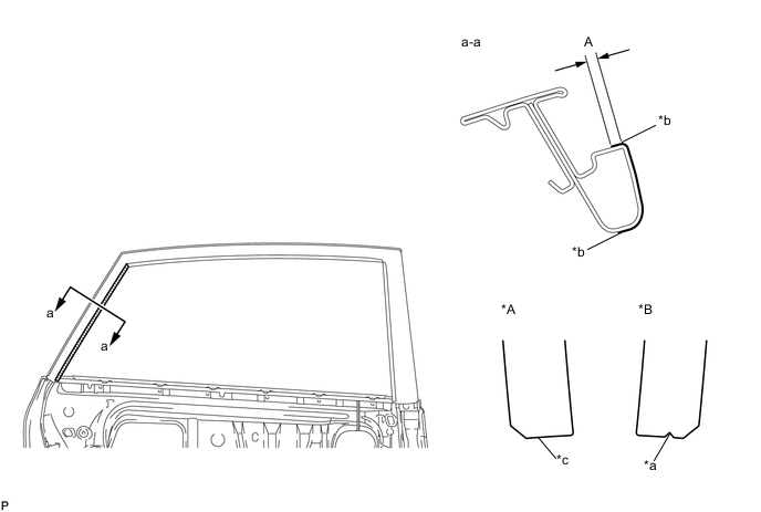
Refer to the illustration to position the rear door outside stripe.
Text in Illustration *A RH Side *B LH Side *a Triangle *b Edge of Curved Surface *c Straight Line - - Standard Measurement Dimension Measurement A 2.0 mm (0.0787 in.) -
Remove the release paper and apply the stripe.
-
-
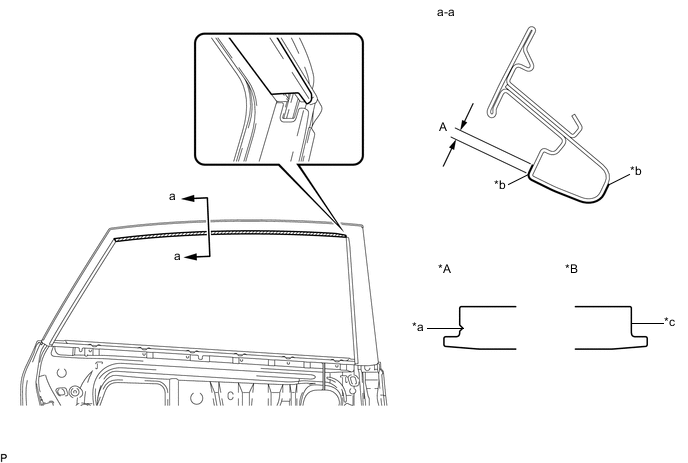
INSTALL REAR DOOR WEATHERSTRIP
-
Engage the clip and install the rear door weatherstrip.
-
-
INSTALL REAR DOOR FRAME GARNISH (w/o Rear Door Sunshade)
-
INSTALL REAR NO. 2 DOOR FRAME GARNISH (w/o Rear Door Sunshade)
-
INSTALL REAR DOOR FRAME GARNISH (w/ Rear Door Sunshade)
-
INSTALL REAR NO. 2 DOOR FRAME GARNISH (w/ Rear Door Sunshade)
-
INSTALL REAR DOOR FRONT WINDOW FRAME MOULDING
-
INSTALL REAR DOOR BELT MOULDING ASSEMBLY
-
INSTALL REAR DOOR GLASS SUB-ASSEMBLY
-
INSTALL REAR DOOR REAR GUIDE SEAL
-
INSTALL REAR DOOR WINDOW GUIDE SUB-ASSEMBLY
-
INSTALL REAR DOOR GLASS RUN
-
INSTALL REAR DOOR SERVICE HOLE COVER
-
INSTALL REAR DOOR TRIM BRACKET
-
INSTALL REAR DOOR TRIM BOARD SUB-ASSEMBLY
-
INSTALL REAR DOOR ARMREST COVER
-
INSTALL REAR POWER WINDOW REGULATOR SWITCH ASSEMBLY WITH REAR DOOR ARMREST BASE PANEL
-
INSTALL REAR DOOR INSIDE HANDLE BEZEL PLUG
-
CONNECT CABLE TO NEGATIVE AUXILIARY BATTERY TERMINAL
Note
When disconnecting the cable, some systems need to be initialized after the cable is reconnected Click here.
-
INSTALL DECK FLOOR BOX RH
-
INSTALL REAR DECK FLOOR BOX
-
INSTALL NO. 1 DECK BOARD
-
INSTALL NO. 2 DECK BOARD
-
INSTALL DECK BOARD ASSEMBLY
-
INITIALIZE POWER WINDOW CONTROL SYSTEM
-
INSPECT POWER WINDOW OPERATION