СИСТЕМА ECD Air Conditioning Cut Control Circuit
DESCRIPTION
This circuit cuts air conditioning operation during vehicle acceleration in order to increase acceleration performance. During acceleration with the vehicle speed at 30 km/h (19 mph) or less and accelerator pedal opening angle at 45° or more, the A/C magnetic switch is turned off for several seconds.
The air conditioning is also controlled by the ECM outputting the engine coolant temperature to A/C amplifier.
WIRING DIAGRAM
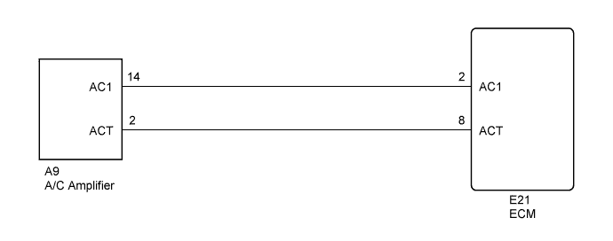
INSPECTION PROCEDURE
When using intelligent tester:
PROCEDURE
-
READ VALUE USING INTELLIGENT TESTER (CHECK OPERATION AIR CONDITIONING CUT CONTROL)
-
Connect the intelligent tester to the DLC3.
-
Start the engine and air conditioning switch ON.
Tech Tips
A/C magnetic clutch is turned ON.
-
Enter the following menus: Powertrain / Engine and ECT / Active Test / A/C Cut SIG.
-
Check operation of A/C magnetic clutch cut when air conditioning cut control is operated by the intelligent tester.
OK A/C magnetic clutch is turned OFF.
OK 
PROCEED TO NEXT CIRCUIT INSPECTION SHOWN IN PROBLEM SYMPTOMS TABLE
NG 
-
-
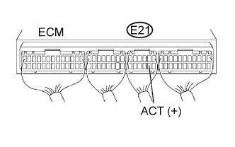
INSPECT ECM (ACT VOLTAGE)
-
Start the engine.
-
Measure the voltage of the ECM connector.
Standard voltage Tester Connection Condition Specified Condition E21-8 (ACT) - Body ground Engine at idling 9 to 14 V E21-8 (ACT) - Body ground Ignition switch ON, Engine stopped 0 to 3 V
OK
REPLACE ECM
NG
-
-
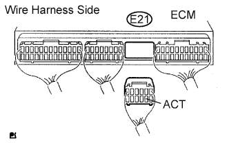
CHECK WIRE HARNESS (ECM - AIR CONDITIONING AMPLIFIER)
-
Disconnect the A9 A/C amplifier connector.
-
Disconnect the E21 ECM connector.
-
Measure the resistance of the wire harness side connectors.
Standard resistance Tester Connection Specified Condition A9-2 (ACT)* - E21-8 (ACT) Below 1 Ω E21-8 (ACT) - Body ground 10 kΩ or higher Tech Tips
*: Terminal arrangement Click here.
NG
REPAIR OR REPLACE HARNESS AND CONNECTOR
OK 
CHECK AND REPLACE AIR CONDITIONING AMPLIFIER
-
When not using intelligent tester:
PROCEDURE
-
CHECK ECM (ACT VOLTAGE)
-
Start the engine.
-
Measure the voltage of the ECM connector.
Standard voltage Tester Connection Condition Specified Condition E21-8 (ACT) - Body ground Engine at idling 9 to 14 V E21-8 (ACT) - Body ground Ignition switch ON, Engine stopped 0 to 3 V
NG 
CHECK WIRE HARNESS (ECM - AIR CONDITIONING AMPLIFIER) Click here
OK
REPLACE ECM
-
-
CHECK WIRE HARNESS (ECM - AIR CONDITIONING AMPLIFIER)
-
Disconnect the A9 A/C amplifier connector.
-
Disconnect the E21 ECM connector.
-
Measure the resistance of the wire harness side connectors.
Standard resistance Tester Connection Specified Condition A9-2 (ACT)* - E21-8 (ACT) Below 1 Ω E21-8 (ACT) - Body ground 10 kΩ or higher Tech Tips
*: Terminal arrangement Click here.
NG
REPAIR OR REPLACE HARNESS AND CONNECTOR
OK
CHECK AND REPLACE AIR CONDITIONING AMPLIFIER
-