IMMOBILISER SYSTEM(w/o Entry and Start System) TERMINALS OF ECU
CHECK TRANSPONDER KEY ECU ASSEMBLY
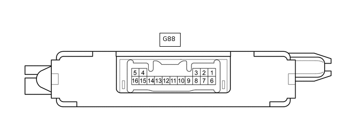
Disconnect the G88 transponder key ECU assembly connector.
Measure the resistance and voltage according to the value(s) in the table below.
Tester Connection
Input/Output
Wiring Color
Terminal Description
Condition
Specified Condition
Related Data List Item
G88-1 (+B) - G88-5 (GND)
Input
BE - BR
Battery
Always
11 to 14 V
+B
G88-2 (IG) - G88-5 (GND)
Input
LG - BR
Ignition switch signal
Ignition switch off
Below 1 V
IG SW
Ignition switch ON
11 to 14 V
G88-3 (KSW) - G88-5 (GND)
Input
P - BR
Unlock warning switch signal
No key in ignition key cylinder
10 kΩ or higher
Key SW/B2780
Key in ignition key cylinder
Below 1 Ω
G88-7 (CTY) - G88-5 (GND)*
Input
W - BR
Driver door courtesy light switch signal
Driver door closed
10 kΩ or higher
D Door Courtesy SW
Driver door open
Below 1 Ω
G88-5 (GND) - Body ground
-
BR - Body ground
Ground
Always
Below 1 Ω
-
*: for key registration when not using GTS
If the result is not as specified, there may be a malfunction on the wire harness side.
Reconnect the G88 transponder key ECU assembly connector.
Measure the voltage and check for pulses according to the value(s) in the table below.
Tester Connection
Input/Output
Wiring Color
Terminal Description
Condition
Specified Condition
Related Data List Item
G88-8 (IND) - G88-5 (GND)
Output
GR - BR
Security indicator signal
No key in ignition key cylinder, or 20 seconds elapsed after turning ignition switch to ACC or off (immobiliser system set)
Pulse generation
Immobiliser
Key in ignition key cylinder (immobiliser system unset)
Below 1 V
G88-9 (D) - G88-5 (GND)
Input/Output
Y - BR
DLC3 communication
Without communication
Below 1 V
-
During communication
Pulse generation
G88-4 (ANT1) - G88-5 (GND)
Input/Output
R - BR
Transponder key amplifier power source
No key in ignition key cylinder
4 to 6 V
-
Within 3 seconds of inserting key into ignition key cylinder
Pulse generation
(See waveform 1)
G88-15 (ANT2) - G88-5 (GND)
Input/Output
W - BR
Transponder key amplifier communication signal
No key in ignition key cylinder
4 to 6 V
-
Within 3 seconds of inserting key into ignition key cylinder
Pulse generation
(See waveform 2)
G88-12 (EFII) - G88-5 (GND)
Output
LG - BR
ECM input signal
Ignition switch off
11 to 14 V
-
Check waveform within 3 seconds of starter operation and initial combustion, or within 3 seconds of ignition switch first being turned to ON after cable disconnected and reconnected to negative (-) battery terminal.
Pulse generation
(See waveform 3)
G88-13 (EFIO) - G88-5 (GND)
Input
P - BR
ECM output signal
Ignition switch off
Below 1 V
-
Check waveform within 3 seconds of starter operation and initial combustion, or within 3 seconds of ignition switch first being turned to ON after cable disconnected and reconnected to negative (-) battery terminal.
Pulse generation
(See waveform 4)
If the result is not as specified, the transponder key ECU assembly may be malfunctioning.
Using an oscilloscope, check the waveform.
Waveform 1 (Reference)
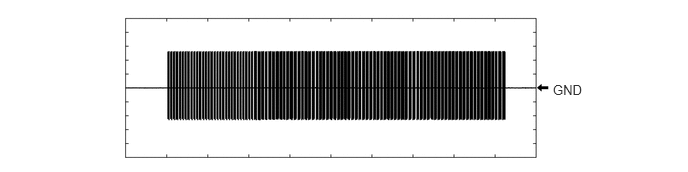
Table 1. Measurement Condition Item
Content
Tester Connection
G88-4 (ANT1) - G88-5 (GND)
Tool Setting
2 V/DIV., 500 ms./DIV.
Condition
Within 3 seconds of inserting key into ignition key cylinder
Waveform 2 (Reference)
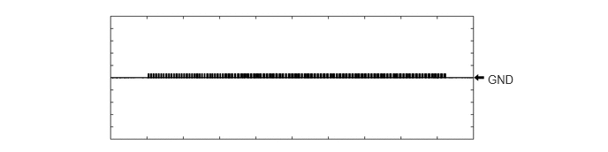
Table 2. Measurement Condition Item
Content
Tester Connection
G88-15 (ANT2) - G88-5 (GND)
Tool Setting
2 V/DIV., 500 ms./DIV.
Condition
Within 3 seconds of inserting key into ignition key cylinder
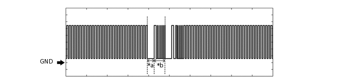
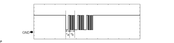
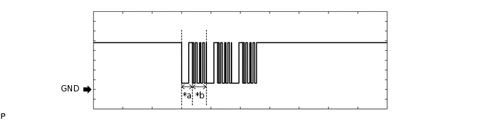
Waveform 3 (Reference)

*a
Approximately 160 ms
*b
Approximately 270 ms
Table 3. Measurement Condition Item
Content
Tester Connection
G88-12 (EFII) - G88-5 (GND)
Tool Setting
2 V/DIV., 500 ms./DIV.
Condition
Check waveform within 3 seconds of starter operation and initial combustion, or within 3 seconds of ignition switch first being turned to ON after cable disconnected and reconnected to negative (-) battery terminal.
Waveform 4 (Reference)
*a
Approximately 160 ms
*b
Approximately 270 ms
Table 4. Measurement Condition Item
Content
Tester Connection
G88-13 (EFIO) - G88-5 (GND)
Tool Setting
2 V/DIV., 500 ms./DIV.
Condition
Check waveform within 3 seconds of starter operation and initial combustion, or within 3 seconds of ignition switch first being turned to ON after cable disconnected and reconnected to negative (-) battery terminal.
-

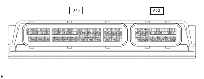
CHECK ECM (for 2AR-FE)
Tip:The standard voltage between each pair of ECM terminals is shown in the table below. The appropriate conditions for checking each pair of terminals are also indicated. The result of checks should be compared with the standard voltage for that pair of terminals, displayed in the "Specified Condition" column. The illustration above can be used as a reference to identify the ECM terminal locations.
Terminal No. (Symbol)
Input/Output
Wiring Color
Terminal Description
Condition
Specified Condition
Related Data List Item/DTC
A62-3 (+B2) - B77-16 (E1)
Input
P - BR
Power source of ECM
Always
11 to 14 V
-
A62-2 (+B) - B77-16 (E1)
Input
R - BR
Power source of ECM
Always
11 to 14 V
-
A62-46 (MREL) - B77-16 (E1)
Input
P - BR
EFI MAIN1 relay
Always
11 to 14 V
-
A62-1 (BATT) - B77-16 (E1)
Input
W - BR
Battery (for measuring battery voltage and for ECM memory)
Always
11 to 14 V
-
B77-16 (E1) - Body ground
-
BR - Body ground
Ground
Always
Below 1 Ω
-
A62-29 (IMO) - B77-16 (E1)
Input
LG - BR
Transponder key ECU assembly communication input
Ignition switch off
Below 1 V*1
11 to 14 V*2
-
A62-29 (IMO) - B77-16 (E1)
Input
LG - BR
Transponder key ECU assembly communication input
Check waveform within 3 seconds of starter operation and initial combustion, or within 3 seconds of ignition switch first being turned to ON after cable disconnected and reconnected to negative (-) battery terminal
Pulse generation (See waveform 1)
-
A62-28 (IMI) - B77-16 (E1)
Output
P - BR
Transponder key ECU assembly communication output
Ignition switch off
Below 1 V
-
A62-28 (IMI) - B77-16 (E1)
Output
P - BR
Transponder key ECU assembly communication output
Check waveform within 3 seconds of starter operation and initial combustion, or within 3 seconds of ignition switch first being turned to ON after cable disconnected and reconnected to negative (-) battery terminal
Pulse generation (See waveform 2)
-
*1: w/ Blocking System
*2: w/o Blocking System
Inspect using an oscilloscope.
Note:The waveform shown in the illustration is an example for reference only. Noise, chattering, etc. are not shown.
Waveform 1 (Reference)
*a
Approximately 160 ms
*b
Approximately 270 ms
Table 5. Measurement Condition Item
Content
Tester Connection
A62-29 (IMO) - B77-16 (E1)
Tool Setting
2 V/DIV., 500 ms./DIV.
Condition
Check waveform within 3 seconds of starter operation and initial combustion, or within 3 seconds of ignition switch first being turned to ON after cable disconnected and reconnected to negative (-) battery terminal
Waveform 2 (Reference)

*a
Approximately 160 ms
*b
Approximately 270 ms
Table 6. Measurement Condition Item
Content
Tester Connection
A62-28 (IMI) - B77-16 (E1)
Tool Setting
2 V/DIV., 500 ms./DIV.
Condition
Check waveform within 3 seconds of starter operation and initial combustion, or within 3 seconds of ignition switch first being turned to ON after cable disconnected and reconnected to negative (-) battery terminal
-
CHECK ECM (for 3ZR-FAE, 3ZR-FE)
Tip:The standard voltage between each pair of ECM terminals is shown in the table below. The appropriate conditions for checking each pair of terminals are also indicated. The result of checks should be compared with the standard voltage for that pair of terminals, displayed in the "Specified Condition" column. The illustration above can be used as a reference to identify the ECM terminal locations.
Terminal No. (Symbol)
Input/Output
Wiring Color
Terminal Description
Condition
Specified Condition
Related Data List Item/DTC
A62-3 (+B2) - B75-16 (E1)
Input
P - BR
Power source of ECM
Always
11 to 14 V
-
A62-2 (+B) - B75-16 (E1)
Input
R - BR
Power source of ECM
Always
11 to 14 V
-
A62-46 (MREL) - B75-16 (E1)
Input
P - BR
EFI MAIN1 relay
Always
11 to 14 V
-
A62-1 (BATT) - B75-16 (E1)
Input
W - BR
Battery (for measuring battery voltage and for ECM memory)
Always
11 to 14 V
-
B75-16 (E1) - Body ground
-
BR - Body ground
Ground
Always
Below 1 Ω
-
A62-29 (IMO) - B75-16 (E1)
Input
LG - BR
Transponder key ECU assembly communication input
Ignition switch off
Below 1 V*1
11 to 14 V*2
-
A62-29 (IMO) - B75-16 (E1)
Input
LG - BR
Transponder key ECU assembly communication input
Check waveform within 3 seconds of starter operation and initial combustion, or within 3 seconds of ignition switch first being turned to ON after cable disconnected and reconnected to negative (-) battery terminal
Pulse generation (See waveform 1)
-
A62-28 (IMI) - B75-16 (E1)
Output
P - BR
Transponder key ECU assembly communication output
Ignition switch off
Below 1 V
-
A62-28 (IMI) - B75-16 (E1)
Output
P - BR
Transponder key ECU assembly communication output
Check waveform within 3 seconds of starter operation and initial combustion, or within 3 seconds of ignition switch first being turned to ON after cable disconnected and reconnected to negative (-) battery terminal
Pulse generation (See waveform 2)
-
*1: w/ Blocking System
*2: w/o Blocking System
Inspect using an oscilloscope.
Note:The waveform shown in the illustration is an example for reference only. Noise, chattering, etc. are not shown.
Waveform 1 (Reference)
*a
Approximately 160 ms
*b
Approximately 270 ms
Table 7. Measurement Condition Item
Content
Tester Connection
A62-29 (IMO) - B75-16 (E1)
Tool Setting
2 V/DIV., 500 ms./DIV.
Condition
Check waveform within 3 seconds of starter operation and initial combustion, or within 3 seconds of ignition switch first being turned to ON after cable disconnected and reconnected to negative (-) battery terminal
Waveform 2 (Reference)
*a
Approximately 160 ms
*b
Approximately 270 ms
Table 8. Measurement Condition Item
Content
Tester Connection
A62-28 (IMI) - B75-16 (E1)
Tool Setting
2 V/DIV., 500 ms./DIV.
Condition
Check waveform within 3 seconds of starter operation and initial combustion, or within 3 seconds of ignition switch first being turned to ON after cable disconnected and reconnected to negative (-) battery terminal
-
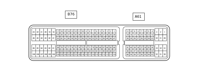
CHECK ECM (for 1AD-FTV, 2AD-FHV, 2AD-DPF, 2AD-CCo)
Tip:The standard voltage between each pair of ECM terminals is shown in the table below. The appropriate conditions for checking each pair of terminals are also indicated. The result of checks should be compared with the standard voltage for that pair of terminals, displayed in the "Specified Condition" column. The illustration above can be used as a reference to identify the ECM terminal locations.
Terminal No. (Symbol)
Input/Output
Wiring Color
Terminal Description
Condition
Specified Condition
Related Data List Item/DTC
A61-20 (+B2) - B76-109 (E1)
Input
B - BR
Power source of ECM
Always
11 to 14 V
-
A61-1 (+B) - B76-109 (E1)
Input
B - BR
Power source of ECM
Always
11 to 14 V
-
A61-45 (MREL) - B76-109 (E1)
Input
B - BR
EFI MAIN1 relay
Always
11 to 14 V
-
A61-2 (BATT) - B76-109 (E1)
Input
W - BR
Battery (for measuring battery voltage and for ECM memory)
Always
11 to 14 V
-
B76-109 (E1) - Body ground
-
BR - Body ground
Ground
Always
Below 1 Ω
-
A61-15 (IMO) - B76-109 (E1)
Input
LG - BR
Transponder key ECU assembly communication input
Ignition switch off
11 to 14 V
-
A61-15 (IMO) - B76-109 (E1)
Input
LG - BR
Transponder key ECU assembly communication input
Check waveform within 3 seconds of starter operation and initial combustion, or within 3 seconds of ignition switch first being turned to ON after cable disconnected and reconnected to negative (-) battery terminal
Pulse generation (See waveform 1)
-
A61-16 (IMI) - B76-109 (E1)
Output
P - BR
Transponder key ECU assembly communication output
Ignition switch off
Below 1 V
-
A61-16 (IMI) - B76-109 (E1)
Output
P - BR
Transponder key ECU assembly communication output
Check waveform within 3 seconds of starter operation and initial combustion, or within 3 seconds of ignition switch first being turned to ON after cable disconnected and reconnected to negative (-) battery terminal
Pulse generation (See waveform 2)
-
Inspect using an oscilloscope.
Note:The waveform shown in the illustration is an example for reference only. Noise, chattering, etc. are not shown.
Waveform 1 (Reference)
*a
Approximately 160 ms
*b
Approximately 270 ms
Table 9. Measurement Condition Item
Content
Tester Connection
A61-15 (IMO) - B76-109 (E1)
Tool Setting
2 V/DIV., 500 ms./DIV.
Condition
Check waveform within 3 seconds of starter operation and initial combustion, or within 3 seconds of ignition switch first being turned to ON after cable disconnected and reconnected to negative (-) battery terminal
Waveform 2 (Reference)
*a
Approximately 160 ms
*b
Approximately 270 ms
Table 10. Measurement Condition Item
Content
Tester Connection
A61-16 (IMI) - B76-109 (E1)
Tool Setting
2 V/DIV., 500 ms./DIV.
Condition
Check waveform within 3 seconds of starter operation and initial combustion, or within 3 seconds of ignition switch first being turned to ON after cable disconnected and reconnected to negative (-) battery terminal
CHECK TELEPHONE TRANSCEIVER ASSEMBLY (w/ Blocking System)
-
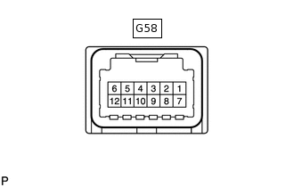
Disconnect the G58 telephone transceiver assembly connector.
Measure the resistance and voltage according to the value(s) in the table below.
Terminal No. (Symbol)
Input/Output
Wiring Color
Terminal Description
Condition
Specified Condition
Related Data List Item/DTC
G58-6 (IG2) - G58-9 (E)
-
SB - W-B
Ignition power supply
Ignition switch ON
9 to 16 V
-
G58-12 (+B) - G58-9 (E)
-
BR - W-B
+B power supply
Always
9 to 16 V
-
G58-9 (E) - Body ground
-
W-B - Body ground
Ground
Always
Below 1 Ω
-
If the result is not as specified, there may be a malfunction on the wire harness side.
Reconnect the G58 telephone transceiver assembly connector.
Measure the voltage according to the value(s) in the table below.
Terminal No. (Symbol)
Input/Output
Wiring Color
Terminal Description
Condition
Specified Condition
Related Data List Item/DTC
G58-1 (BLK1) - G58-9 (E)
Input
LG - W-B
Transponder key ECU assembly communication input
Ignition switch off
11 to 14 V
-
G58-1 (BLK1) - G58-9 (E)
Input
LG - W-B
Transponder key ECU assembly communication input
Check waveform within 3 seconds of starter operation and initial combustion, or within 3 seconds of ignition switch first being turned to ON after cable disconnected and reconnected to negative (-) battery terminal
Pulse generation (See waveform 1)
-
G58-2 (BLK4) - G58-9 (E)
Output
P - W-B
Transponder key ECU assembly communication output
Ignition switch off
Below 1 V
-
G58-2 (BLK4) - G58-9 (E)
Output
P - W-B
Transponder key ECU assembly communication output
Check waveform within 3 seconds of starter operation and initial combustion, or within 3 seconds of ignition switch first being turned to ON after cable disconnected and reconnected to negative (-) battery terminal
Pulse generation (See waveform 2)
-
G58-7 (BLK2) - G58-9 (E)
Output
LG - W-B
ECM communication output
Ignition switch off
Below 1 V
-
G58-7 (BLK2) - G58-9 (E)
Output
LG - W-B
ECM communication output
Check waveform within 3 seconds of starter operation and initial combustion, or within 3 seconds of ignition switch first being turned to ON after cable disconnected and reconnected to negative (-) battery terminal
Pulse generation (See waveform 1)
-
G58-8 (BLK3) - G58-9 (E)
Input
P - W-B
ECM communication input
Ignition switch off
Below 1 V
-
G58-8 (BLK3) - G58-9 (E)
Input
P - W-B
ECM communication input
Check waveform within 3 seconds of starter operation and initial combustion, or within 3 seconds of ignition switch first being turned to ON after cable disconnected and reconnected to negative (-) battery terminal
Pulse generation (See waveform 2)
-
Inspect using an oscilloscope.
Note:The waveform shown in the illustration is an example for reference only. Noise, chattering, etc. are not shown.
Waveform 1 (Reference)
*a
Approximately 160 ms
*b
Approximately 270 ms
Table 11. Measurement Condition Item
Content
Tester Connection
G58-1 (BLK1) - G58-9 (E)
G58-7 (BLK2) - G58-9 (E)
Tool Setting
2 V/DIV., 500 ms./DIV.
Condition
Check waveform within 3 seconds of starter operation and initial combustion, or within 3 seconds of ignition switch first being turned to ON after cable disconnected and reconnected to negative (-) battery terminal
Waveform 2 (Reference)

*a
Approximately 160 ms
*b
Approximately 270 ms
Table 12. Measurement Condition Item
Content
Tester Connection
G58-2 (BLK4) - G58-9 (E)
G58-8 (BLK3) - G58-9 (E)
Tool Setting
2 V/DIV., 500 ms./DIV.
Condition
Check waveform within 3 seconds of starter operation and initial combustion, or within 3 seconds of ignition switch first being turned to ON after cable disconnected and reconnected to negative (-) battery terminal
-