SFI SYSTEM(w/ Canister Pump Module) DATA LIST / ACTIVE TEST
DATA LIST
Tip:Using the GTS to read the Data List allows the values or states of switches, sensors, actuators and other items to be read without removing any parts. This non-intrusive inspection can be very useful because intermittent conditions or signals may be discovered before parts or wiring is disturbed. Reading the Data List information early in troubleshooting is one way to save diagnostic time.
Note:In the table below, the values listed under "Normal Condition" are reference values. Do not depend solely on these reference values when deciding whether a part is faulty or not.
The actual values may differ from the values listed in the chart under "Results of real-vehicle check" due to climate, weather conditions, etc.
Tip:Normal Condition: If no conditions are specifically stated for "idling", the shift lever should be in N or P, the A/C switch should be off and all accessory switches should be off.
Warm up the engine.
Turn the A/C switch off.
Turn the engine switch off.
Connect the GTS to the DLC3.
Turn the engine switch on (IG).
Turn the GTS on.
Enter the following menus: Powertrain / Engine and ECT / Data List.
Tip:To display the list box, press the pull down menu button next to Primary. Then select a measurement group.
When you select a measurement group, the ECU data belonging to that group is displayed.
Measurement Group List / Description
-
All Data / All data
Primary / -
Engine Control / Engine control system related data
Ptrl General / -
Ptrl AF Control / Air fuel ratio control system related data
Ptrl AF O2 Sensor / Air fuel ratio sensor and heated oxygen sensor related data
Ptrl Throttle / Ptrloline throttle system related data
Ptrl / Intake control / Intake control system related data
Ptrl Valve Control / Valve control system related data
Ptrl Misfire / "Misfire" related data
Ptrl Starting / "Difficult to start" related data
Ptrl Rough Idle / "Rough idle" related data
Ptrl Evaporative / Evaporative system related data
Ptrl CAT Converter / Catalyst converter related data
Check Mode / Check mode related data
Monitor Status / Monitor status related data
Ignition / Ignition system related data
Charging Control / Charging control system related data
Compression / Data used during "Check the Cylinder Compression" Active Test
AT / Automatic transaxle system related data
Vehicle Information / Vehicle information
According to the display on the GTS, read the Data List.
Tip:The title used for each group of Data List items in this repair manual does not appear on the GTS. However, the name in parentheses after the title, which is a Measurement Group, does appear on the GTS. When the name shown in parentheses is selected on the GTS, all the Data List items listed for that group will be displayed.
"Result of real-vehicle check" is the assessment of one vehicle. Use it only for reference.
Various Vehicle Conditions 1 (All Data)
Powertrain > Engine and ECT > Data List
Tester Display
Measurement Item
Range
Normal Condition
Reference Value
Diagnostic Note
Vehicle Speed
Vehicle speed
Min.: 0 km/h (0 mph), Max.: 255 km/h (158 mph)
Actual vehicle speed
-
Stored as Freeze Frame Data: Yes
This is the current vehicle speed.
The vehicle speed is detected using the wheel speed sensors.
-
Vehicle speed data is delayed when it is displayed. Therefore, even if the vehicle speed listed in the freeze frame data is 0 km/h (0 mph), this does not always mean that the malfunction occurred when the vehicle was stopped.
Engine Speed
Engine speed
Min.: 0 rpm, Max.: 16383 rpm
720 to 820 rpm: Idling
Idling (engine warmed up and A/C off): 770 rpm
Stored as Freeze Frame Data: Yes
When the crankshaft position sensor is malfunctioning, "Engine Speed" is approximately 0 rpm or varies greatly from the actual engine speed.
Calculate Load
Load calculated by ECM
Min.: 0%, Max.: 100%
-
Engine switch on (IG): 0.0%
Idling (engine warmed up): 28.2%
Running without load (3000 rpm): 27.2%
Stored as Freeze Frame Data: Yes
This is the engine load calculated based on the estimated intake manifold pressure.
Calculate Load = Estimated intake manifold pressure / maximum intake manifold pressure x 100 (%)
(For example, when the estimated intake pressure is the same as atmospheric pressure, Calculate Load is 100%.)
Vehicle Load
Vehicle load
Min.: 0%, Max.: 25700%
-
Engine switch on (IG): 0.0%
Idling (engine warmed up): 14.1%
Running without load (3000 rpm): 14.5%
Stored as Freeze Frame Data: Yes
This is the engine intake air charging efficiency.
Vehicle Load = Current intake airflow (g/rev.) / maximum intake airflow
Maximum intake airflow = Displacement (L) / 2 x 1.2 (g/rev.)
Tip:Due to individual engine differences, intake air temperature, etc., the value may exceed 100%.
Intake airflow (g/rev.) = Intake airflow (gm/sec) x 60 / Engine speed (rpm)
(Intake airflow (gm/sec) is MAF)
MAF
Airflow rate from mass air flow meter sub-assembly
Min.: 0 gm/sec, Max.: 655.35 gm/sec
1.0 to 3.0 gm/sec: Idling
8 to 22 gm/sec: 3000 rpm (without load)
Engine switch on (IG): 0.51 gm/sec
Idling (engine warmed up): 2.54 gm/sec
Running without load (2500 rpm): 8.57 gm/sec
Running without load (3000 rpm): 10.98 gm/sec
Stored as Freeze Frame Data: Yes
This is the intake air amount from the mass air flow meter sub-assembly.
Atmosphere Pressure
Atmospheric pressure
Min.: 0 kPa (0 mmHg), Max.: 255 kPa (1912 mmHg)
Equivalent to atmospheric pressure (absolute pressure)
Idling (engine warmed up): 100 kPa(abs) [750 mmHg(abs)]
Stored as Freeze Frame Data: Yes
This value is calculated from the intake air amount.
Standard atmospheric pressure: 101 kPa(abs) [760 mmHg(abs)]
For every 100 m (328 ft) increase in altitude, pressure drops by 1 kPa (7.5 mmHg). This varies by weather.
Coolant Temp
Coolant temperature
Min.: -40°C (-40°F), Max.: 140°C (284°F)
75 to 100°C (167 to 212°F): After warming up
-
Stored as Freeze Frame Data: Yes
This is the engine coolant temperature.
Tip:After warming up the engine, the engine coolant temperature is 75 to 100°C (167 to 212°F).
After a long soak, the engine coolant temperature, intake air temperature and ambient air temperature are approximately equal.
If the value is -40°C (-40°F), or higher than 135°C (275°F), the sensor circuit is open or shorted.
Check if the engine overheats when the value indicates higher than 135°C (275°F).
Intake Air
Intake air temperature
Min.: -40°C (-40°F), Max.: 140°C (284°F)
Equivalent to temperature at location of mass air flow meter sub-assembly
-
Stored as Freeze Frame Data: Yes
After a long soak, the engine coolant temperature, intake air temperature and ambient air temperature are approximately equal.
If the value is -40°C (-40°F), or higher than 128°C (262°F), the sensor circuit is open or shorted.
Engine Run Time
Engine run time
Min.: 0 s, Max.: 65535 s
Time after engine start
-
Stored as Freeze Frame Data: Yes
This is the time elapsed since the engine started.
Tip:The time is counted only while the engine is running.
Initial Engine Coolant Temp
Initial engine coolant temperature
Min.: -40°C (-40°F), Max.: 119.3°C (247°F)
-
-
Stored as Freeze Frame Data: Yes
This is the coolant temperature stored when the engine switch is turned on (IG).
Initial Intake Air Temp
Initial intake air temperature
Min.: -40°C (-40°F), Max.: 119.3°C (247°F)
-
-
Stored as Freeze Frame Data: Yes
This is the intake air temperature stored when the engine switch is turned on (IG).
Battery Voltage
Battery voltage
Min.: 0 V, Max.: 65.535 V
11 to 14 V: Idling
Engine switch on (IG): 11.679 V
Cranking: 11.523 V
Idling (engine warmed up): 13.457 V
Stored as Freeze Frame Data: Yes
If 11 V or less, characteristics of some electrical components may change.
Glow Indicator Supported
Status of the glow indicator supported
Unsupported or Supported
Unsupported
-
Stored as Freeze Frame Data: Yes
Glow Indicator
Status of the glow indicator
ON or OFF
OFF
-
Stored as Freeze Frame Data: Yes
Throttle Control 1 (Ptrl Throttle)
Powertrain > Engine and ECT > Data List
Tester Display
Measurement Item
Range
Normal Condition
Reference Value
Diagnostic Note
Accelerator Position
Accelerator pedal position
Min.: 0%, Max.: 399.9%
Actual accelerator pedal position
Engine switch on (IG): 0.0% (accelerator pedal fully released)
Engine switch on (IG): 100.0% (accelerator pedal fully depressed)
Stored as Freeze Frame Data: No
This is the accelerator pedal position defined using the learned fully released position (sensor output) of accelerator pedal position sensor No. 1 as 0% and the fully depressed position as 100%.
Accel Sens. No.1 Volt %
Absolute accelerator pedal position No. 1
Min.: 0%, Max.: 100%
10 to 22%: Accelerator pedal fully released
52 to 90%: Accelerator pedal fully depressed
Engine switch on (IG): 15.6% (accelerator pedal fully released)
Engine switch on (IG): 70.9% (accelerator pedal fully depressed)
Stored as Freeze Frame Data: Yes
The accelerator pedal position sensor No. 1 output is converted using 5 V = 100%.
Tip:If there are no accelerator pedal position sensor DTCs stored, it is possible to conclude that the accelerator pedal position sensor system is normal.
Accel Sens. No.2 Volt %
Absolute accelerator pedal position No. 2
Min.: 0%, Max.: 100%
24 to 40%: Accelerator pedal fully released
68 to 95%: Accelerator pedal fully depressed
Engine switch on (IG): 31.7% (accelerator pedal fully released)
Engine switch on (IG): 87.8% (accelerator pedal fully depressed)
Stored as Freeze Frame Data: Yes
The accelerator pedal position sensor No. 2 output is converted using 5 V = 100%.
Throttle Control 2 (All Data)
Powertrain > Engine and ECT > Data List
Tester Display
Measurement Item
Range
Normal Condition
Reference Value
Diagnostic Note
Accel Sensor Out No.1
Accelerator pedal position sensor No. 1 voltage
Min.: 0 V, Max.: 4.98 V
0.5 to 1.1 V: Accelerator pedal fully released
2.6 to 4.5 V: Accelerator pedal fully depressed
Engine switch on (IG): 0.781 V (accelerator pedal fully released)
Engine switch on (IG): 3.535 V (accelerator pedal fully depressed)
Stored as Freeze Frame Data: No
This is the raw voltage from the accelerator pedal position sensor No. 1.
Accel Sensor Out No.2
Accelerator pedal position sensor No. 2 voltage
Min.: 0 V, Max.: 4.98 V
1.2 to 2.0 V: Accelerator pedal fully released
3.4 to 4.75 V: Accelerator pedal fully depressed
Engine switch on (IG): 1.582 V (accelerator pedal fully released)
Engine switch on (IG): 4.375 V (accelerator pedal fully depressed)
Stored as Freeze Frame Data: No
This is the raw voltage from the accelerator pedal position sensor No. 2.
Accelerator pedal position sensor No. 2 is used to monitor accelerator pedal position sensor No. 1. When there is a malfunction in sensor No. 1, the ECM uses sensor No. 2 to control the engine.
Throttle Control 3 (Ptrl Throttle)
Powertrain > Engine and ECT > Data List
Tester Display
Measurement Item
Range
Normal Condition
Reference Value
Diagnostic Note
Accelerator Idle Position
Whether or not accelerator pedal position sensor detecting released accelerator pedal
ON or OFF
ON: Accelerator pedal fully released
Engine switch on (IG): ON (accelerator pedal fully released)
Engine switch on (IG): OFF (accelerator pedal depressed)
Stored as Freeze Frame Data: No
This is a parameter calculated by the ECM which indicates whether the accelerator pedal is in the learned idle position.
Accel Fully Close Learn #1
Accelerator fully released learned value No. 1
Min.: 0 deg, Max.: 124.5 deg
-
Engine switch on (IG): 19.5 deg
Stored as Freeze Frame Data: No
This is the value of accelerator pedal position sensor No. 1 learned when the accelerator pedal is released.
Accel Fully Close Learn #2
Accelerator fully released learned value No. 2
Min.: 0 deg, Max.: 124.5 deg
-
Engine switch on (IG): 39.5 deg
Stored as Freeze Frame Data: No
This is the value of accelerator pedal position sensor No. 2 learned when the accelerator pedal is released.
Throttle Sensor Volt %
Absolute throttle position sensor No. 1
Min.: 0%, Max.: 100%
10 to 22%: Accelerator pedal fully released
64 to 96%: Accelerator pedal fully depressed
Engine switch on (IG): 18.4% (accelerator pedal fully released)
Tip:The throttle valve is not completely closed, but is kept open a certain amount by the throttle valve opener.
Engine switch on (IG): 82.3% (accelerator pedal fully depressed)
Idling (engine warmed up): 14.9%
Running without load (3000 rpm): 19.2%
Stored as Freeze Frame Data: Yes
The throttle position sensor No. 1 output is converted using 5 V = 100%.
Tip:If there are no throttle position sensor DTCs stored, it is possible to conclude that the throttle position sensor system is normal.
Throttl Sensor #2 Volt %
Throttle sensor position No. 2
Min.: 0%, Max.: 100%
42 to 62%: Accelerator pedal fully released
92 to 100%: Accelerator pedal fully depressed
Engine switch on (IG): 50.5% (accelerator pedal fully released)
Tip:The throttle valve is not completely closed, but is kept open a certain amount by the throttle valve opener.
Engine switch on (IG): 99.6% (accelerator pedal fully depressed)
Idling (engine warmed up): 46.6%
Stored as Freeze Frame Data: Yes
The throttle position sensor No. 2 output is converted using 5 V = 100%.
ST1
Brake pedal signal
ON or OFF
ON: Brake pedal depressed
OFF: Brake pedal fully released
-
Stored as Freeze Frame Data: No
This is the stop light switch assembly signal (ST1- terminal).
System Guard
System guard
ON or OFF
ON
Idling (engine warmed up): ON
Stored as Freeze Frame Data: No
When there is a difference between the target and actual throttle valve opening angles, system guard turns off and stops the electronic throttle control system function.
OFF: Electronic throttle control is stopped.
Open Side Malfunction
Open malfunction
ON or OFF
OFF
-
Stored as Freeze Frame Data: No
This parameter indicates a malfunction in the electronic throttle when the throttle valve is open.
Throttle Idle Position
Whether or not throttle position sensor detecting idle
ON or OFF
-
Engine switch on (IG): ON
Tip:The throttle valve is not completely closed, but is kept open a certain amount by the throttle valve opener.
Idling (engine warmed up): ON
Running without load (3000 rpm): OFF
Stored as Freeze Frame Data: No
This is a parameter calculated by the ECM.
The value is ON when the throttle is at the idle position and OFF when the throttle is open.
Throttle Require Position
Required throttle position
Min.: 0 V, Max.: 4.98 V
-
Engine switch on (IG): 0.82 V (accelerator pedal fully released)
Engine switch on (IG): 4.10 V (accelerator pedal fully depressed)
Idling (engine warmed up): 0.72 V
Stored as Freeze Frame Data: No
This is a value calculated by the ECM showing the voltage for the target throttle valve position. It is almost an exact match of the Throttle Position No. 1 value except during very rapid throttle valve movement, such as that used during wheelspin control.
Throttle Sensor Position
Throttle sensor position
Min.: 0%, Max.: 100%
0%: Accelerator pedal fully released
50 to 80%: Accelerator pedal fully depressed
Idling (engine warmed up): 0.0%
Stored as Freeze Frame Data: Yes
This is the throttle valve opening amount used for engine control.
(100% signifies 125° of throttle valve rotation. This does not include the amount the throttle valve is opened to maintain the idle speed during idling.)
This value has no meaning when the engine switch is turn to on (IG) and the engine is stopped.
The throttle valve opening amount during idling is indicated by 0%. When the throttle valve is fully open, the value is 68%.
Throttle Position No.1
Throttle position sensor No. 1 output voltage
Min.: 0 V, Max.: 4.98 V
Almost same as "Throttle Require Position"
0.5 to 1.1 V: Accelerator pedal fully released
3.2 to 4.8 V: Accelerator pedal fully depressed
0.6 to 1.4 V: Fail-safe operating
Engine switch on (IG): 0.82 V (accelerator pedal fully released)
Engine switch on (IG): 4.10 V (accelerator pedal fully depressed)
Idling (engine warmed up): 0.72 V
Stored as Freeze Frame Data: No
This is the throttle position sensor No. 1 output voltage.
Throttle Position No.2
Throttle position sensor No. 2 output voltage
Min.: 0 V, Max.: 4.98 V
2.1 to 3.1 V: Accelerator pedal fully released
4.6 to 4.98 V: Accelerator pedal fully depressed
2.1 to 3.1 V: Fail-safe operating
Engine switch on (IG): 2.42 V (accelerator pedal fully released)
Engine switch on (IG): 4.94 V (accelerator pedal fully depressed)
Idling (engine warmed up): 2.30 V
Stored as Freeze Frame Data: No
This is the throttle position sensor No. 2 output voltage.
Throttle Position Command
Throttle position command value
Min.: 0 V, Max.: 4.98 V
-
-
Stored as Freeze Frame Data: No
Throttle Position Command is the same value as Throttle Require Position.
Throttle Sens Open Pos #1
Throttle position sensor No. 1
Min.: 0 V, Max.: 4.98 V
0.6 to 1.4 V
Engine switch on (IG): 0.917 V
Stored as Freeze Frame Data: No
This is the throttle position sensor No. 1 output voltage when there is no current supplied to the electronic throttle actuator. The accelerator pedal is released but the throttle valve is kept open by the throttle valve opener with the engine switch on (IG).
Throttle Sens Open Pos #2
Throttle position sensor No. 2
Min.: 0 V, Max.: 4.98 V
1.7 to 2.5 V
Engine switch on (IG): 2.01 V
Stored as Freeze Frame Data: No
This is the throttle position sensor No. 2 output voltage when there is no current supplied to the electronic throttle actuator. The accelerator pedal is released but the throttle valve is kept open by the throttle valve opener with the engine switch on (IG).
Throttle Motor Current
Throttle actuator current
Min.: 0 A, Max.: 19.9 A
0 to 3.0 A: Idling
Engine switch on (IG): 0.7 A (accelerator pedal fully released)
Engine switch on (IG): 0.8 A (accelerator pedal fully depressed)
Idling (engine warmed up): 0.7 A
Running without load (3000 rpm): 0.7 A
Stored as Freeze Frame Data: No
When this value is large but the actual opening angle (Throttle Position No. 1) does not reach the target opening angle (Throttle Require Position), there is an "unable to open" malfunction.
This value normally fluctuates around 1 A.
Throttle Motor DUTY
Throttle actuator
Min.: 0%, Max.: 100%
10 to 22%: Idling
-
Stored as Freeze Frame Data: Yes
This is the output duty ratio of the throttle actuator drive circuit.
Throttle Motor Duty (Open)
Throttle actuator duty ratio (open)
Min.: 0%, Max.: 255%
0 to 40%: Idling
Engine switch on (IG): 0% (accelerator pedal fully released)
Engine switch on (IG): 16% (accelerator pedal fully depressed)
Idling (engine warmed up): 0%
Running without load (3000 rpm): 10%
Stored as Freeze Frame Data: No
This is the duty ratio used to drive the throttle actuator and open the throttle valve. It is an ECM command signal.
When the throttle valve is being opened, Throttle Motor Duty (Open) is 10 to 50%.
Throttle Motor Duty (Close)
Throttle actuator duty ratio (close)
Min.: 0%, Max.: 255%
0 to 40%: Idling
Engine switch on (IG): 12% (accelerator pedal fully released)
Engine switch on (IG): 0% (accelerator pedal fully depressed)
Idling (engine warmed up): 12%
Running without load (3000 rpm): 0%
Stored as Freeze Frame Data: No
This is the duty ratio used to drive the throttle actuator and close the throttle valve. It is an ECM command signal.
Tip:During idling, the throttle valve opening angle is usually controlled using a duty ratio drive signal which closes the throttle valve. However, when carbon deposits build up, it may be necessary to open the throttle valve more than the throttle valve opener does. In that case, the opening angle is controlled using a "Throttle Motor Duty (Open)" signal which opens the throttle valve.
Throttle Fully Close Learn
Throttle valve fully closed position (learned value)
Min.: 0 V, Max.: 4.98 V
0.4 to 1.0 V: Accelerator pedal fully released
Engine switch on (IG): 0.625 V
Stored as Freeze Frame Data: No
The ECM uses this learned value to determine the fully closed (and fully open) position of the throttle valve. This learned value is calculated by the ECM with the throttle valve opener angle (approximately 4 to 7°, the position when the engine switch is turned on (IG), the accelerator pedal is released and the throttle actuator is off).
Learning is performed immediately after the engine switch is turned on (IG).
+BM Voltage
+BM voltage
Min.: 0 V, Max.: 79.998 V
11 to 14 V: Engine switch on (IG) and system normal
-
Stored as Freeze Frame Data: No
This is the power supply for the electronic throttle actuator. When the power supply is interrupted for approximately 1 second, DTCs P2118 (open circuit) and P0657 (short circuit, ECU malfunction) are stored and the electronic throttle control system enters fail-safe mode (normal operation is not restored until the engine switch is turned off).
Actuator Power Supply
Actuator power supply
ON or OFF
ON: Idling
-
Stored as Freeze Frame Data: No
If +BM power is lost, this item changes to OFF.
Throttle Position
Throttle valve opening angle
Min.: 0 deg, Max.: 499.99 deg
-
Idling (engine warmed up): 0.00 deg
Stored as Freeze Frame Data: Yes
This value has no meaning when the engine switch is turned on (IG) and the engine is stopped.
Idle Speed Control (Ptrl Rough Idle)
Powertrain > Engine and ECT > Data List
Tester Display
Measurement Item
Range
Normal Condition
Reference Value
Diagnostic Note
ISC Flow
Flow rate calculated using information from mass air flow meter sub-assembly
Min.: 0 L/s, Max.: 79.99 L/s
-
Idling (engine warmed up): 2.40 L/s
Stored as Freeze Frame Data: Yes
This is the total ISC airflow amount (the amount of intake air necessary to maintain idling).
Tip:ISC Flow (total ISC airflow amount) = ISC Learning Value + ISC Feedback Value + each compensation amount
ISC Position
Requested throttle opening amount calculated using ISC control
Min.: 0 deg, Max.: 499.99 deg
-
Idling (engine warmed up): 3.11 deg
Stored as Freeze Frame Data: Yes
This is the throttle valve opening amount while the engine is idling (the throttle valve opening amount necessary to maintain ISC air flow).
ISC Feedback Value
ISC feedback amount
Min.: -40 L/s, Max.: 39.99 L/s
-
Idling (engine warmed up): -0.12 L/s
Stored as Freeze Frame Data: Yes
This is the feedback amount necessary to adjust the airflow amount to maintain the target idle speed.
Tip:When the idle speed differs from the target, the feedback amount is adjusted. If the feedback amount becomes more than a certain value, this will be reflected in the ISC learned airflow value.
ISC Learning Value
ISC learned airflow value
Min.: -40 L/s, Max.: 39.99 L/s
-
Idling (engine warmed up): 1.84 L/s
Stored as Freeze Frame Data: Yes
This is the learned value of the airflow amount necessary for engine idling.
Tip:If ISC Feedback Value becomes more than a certain value, this will be reflected in ISC Learning Value.
ISC Flow (total ISC airflow amount) = ISC Learning Value + ISC Feedback Value + each compensation amount
Electric Load Feedback Val
Compensation flow rate according to electrical load
Min.: -40 L/s, Max.: 39.99 L/s
-
Idling (headlights and window defogger on): 0.04 L/s
Stored as Freeze Frame Data: Yes
This is the ISC compensation amount determined according to the electrical load.
Air Conditioner FB Val
Compensation flow rate according to air conditioner load
Min.: -40 L/s, Max.: 39.99 L/s
-
Idling (A/C on): 0.66 L/s
Stored as Freeze Frame Data: Yes
This is the ISC compensation amount determined according to the air conditioner load.
Low Revolution Control
Low engine speed control operation state
ON or OFF
-
Idling (engine warmed up): OFF
Stored as Freeze Frame Data: Yes
This parameter indicates whether the engine speed dropped immediately after starting due to poor combustion, etc. This parameter changes to ON when the engine speed drops to below the following speeds 1 to 7 seconds after the engine is started (when the A/C is on, the engine speed thresholds below increase by 100 to 200 rpm).
-
900 rpm (when the engine coolant temperature is 10°C (50°F)).
850 rpm (when the engine coolant temperature is 30°C (86°F)).
750 rpm (when the engine coolant temperature is 60°C (140°F)).
Before 5 seconds elapse after starting the engine, this parameter indicates the status of the previous trip.
After 5 seconds elapse after starting the engine, this parameter indicates the status of the current trip.
Tip:The engine is considered to have started when the engine speed reaches 400 rpm. When the engine speed decreases immediately after starting the engine, this parameter changes to ON and remains ON for the rest of the trip.
ON: The engine speed decreased immediately after starting the engine.
OFF: The engine speed did not decrease immediately after starting the engine.
For use when engine stall, starting problems or rough idle is present.
N Range Status
Shift lever N status
ON or OFF
-
-
Stored as Freeze Frame Data: Yes
Eng Stall Control FB Flow
Intake air compensation flow rate
Min.: -40 L/s, Max.: 39.99 L/s
-
Idling (engine warmed up): 0.00 L/s
Stored as Freeze Frame Data: Yes
The intake air amount and ignition timing are adjusted when there is a large decrease in engine speed (for example, a decrease to 550 rpm or less) in order to prevent engine stall.
For use when engine stall, starting problems or rough idle is present.
Deposit Loss Flow
Flow loss due to deposits
Min.: -40 L/s, Max.: 39.99 L/s
-
Idling (engine warmed up): 0.00 L/s
Stored as Freeze Frame Data: Yes
This value indicates the amount of compensation for a decrease in flow passage area due to the buildup of deposits on the throttle valve.
Check this value for reference when the engine stalls, is difficult to start, or idles roughly.
When the ISC learned value is initialized, perform the following procedures in order to quickly relearn the Deposit Loss Flow value. After the Deposit Loss Flow has been relearned, gradual fine adjustments will continue automatically.
-
Start the engine cold and allow the engine to idle.
After the engine is warmed up (engine coolant temperature is above 80°C [176°F]), allow the engine to idle for an additional 5 minutes.
Turn the engine switch off and wait for 30 seconds.
Start the engine again, and allow the engine to idle for 5 minutes.
Fuel System 1 (Ptrl General)
Powertrain > Engine and ECT > Data List
Tester Display
Measurement Item
Range
Normal Condition
Reference Value
Diagnostic Note
Fuel Pump Duty
Fuel pump duty
Min.: 0%, Max.: 399.9%
-
Idling (engine warmed up): 76.0%
Running without load (3000 rpm): 76.0%
Stored as Freeze Frame Data: Yes
This item is displayed only with fuel pump control ECU assembly.
Injector (Port)
Injection period of the No. 1 cylinder
Min.: 0 μs, Max.: 65535 μs
-
Idling (engine warmed up): 2332 μs
Running without load (3000 rpm): 2293 μs
Stored as Freeze Frame Data: Yes
This is the injection period of the No. 1 cylinder (the command value from the ECM).
Injection Volum (Cylinder1)
Injection volume (cylinder 1)
Min.: 0 ml, Max.: 2.047 ml
0 to 0.5 ml
Idling (engine warmed up): 0.108 ml
Running without load (3000 rpm): 0.097 ml
Stored as Freeze Frame Data: Yes
This is the fuel injection volume for 10 injections.
Fuel Pump/Speed Status
Fuel pump status
ON or OFF
ON: Starter on or engine running
-
Stored as Freeze Frame Data: Yes
EVAP System 1 (All Data)
Powertrain > Engine and ECT > Data List
Tester Display
Measurement Item
Range
Normal Condition
Reference Value
Diagnostic Note
Vacuum Pump
Key-off EVAP system leak detection pump status
ON or OFF
-
-
Stored as Freeze Frame Data: Yes
This item changes to ON during the key-off EVAP monitor which is performed approximately 5 hours after the engine switch is turned off*.
Intake Control 1 (Ptrl Intake Control)
Powertrain > Engine and ECT > Data List
Tester Display
Measurement Item
Range
Normal Condition
Reference Value
Diagnostic Note
TCV Status
Intake air control valve actuator for tumble control valve status
ON or OFF
ON: Cold engine start
-
Stored as Freeze Frame Data: Yes
This item changes to ON while the tumble control valve is closed.
Fuel System 2 (Ptrl General)
Powertrain > Engine and ECT > Data List
Tester Display
Measurement Item
Range
Normal Condition
Reference Value
Diagnostic Note
Current Fuel Type
Current fuel type
-
Gasoline/petrol
-
Stored as Freeze Frame Data: Yes
EVAP System 2 (Ptrl Evaporative)
Powertrain > Engine and ECT > Data List
Tester Display
Measurement Item
Range
Normal Condition
Reference Value
Diagnostic Note
EVAP (Purge) VSV
Purge VSV control duty
Min.: 0%, Max.: 100%
-
Idling (engine warmed up): 0.0%
Running without load (3000 rpm): 30.5%
Stored as Freeze Frame Data: Yes
This is the command signal from the ECM.
This is the purge VSV control duty ratio. When EVAP (Purge) VSV is any value except 0%, EVAP purge* is being performed.
*: Gasoline vapor from the fuel tank is being introduced into the intake system via the purge VSV.
When the engine is cold or immediately after the engine is started, EVAP (Purge) VSV is 0%.
Evap Purge Flow
Purge flow
Min.: 0%, Max.: 399.9%
-
Idling (engine warmed up): 0.0%
Running without load (3000 rpm): 2.5%
Stored as Freeze Frame Data: Yes
This is the percentage of total engine airflow contributed by EVAP purge operation.
(Evap Purge Flow = Purge flow / Engine airflow x 100 (%))
It is based on MAF and a stored value for airflow and controlled by adjusting the duty cycle for the purge VSV.
Purge Density Learn Value
Purge density learned value
Min.: -200, Max.: 199.993
-
Idling (engine warmed up): 0.00
Stored as Freeze Frame Data: Yes
Purge Density Learn Value is the proportion of the decrease in injection volume (based on the change in the air fuel ratio feedback compensation value) related to a 1% purge flow rate.
When Purge Density Learn Value is a large negative value, the purge effect is large.
The purge density is determined from the change in the air fuel ratio feedback compensation value when purge flow is introduced.
Purge density learning is performed so that the feedback compensation value is 0 +/-2%.
Tip:Usually, the value is approximately +/-1%.
1%: The concentration of HC in the purge gas is relatively low.
0%: The concentration of HC in the purge gas is approximately equal to the stoichiometric air fuel ratio.
Large negative values indicate that the concentration of HC in the purge gas is relatively high.
Vapor Pressure Pump
Vapor pressure
Min.: 0 kPa (0 mmHg), Max.: 1441.77 kPa (10814.17 mmHg)
Approximately 100 kPa(abs) [750 mmHg(abs)]: Engine switch on (IG)
-
Stored as Freeze Frame Data: No
This is the EVAP system pressure monitored by the canister pressure sensor.
Tip:Except for when the monitor is running, this value should be approximately the same as atmospheric pressure.
As Vapor Pressure Pump is almost the same as atmospheric pressure when the engine is stopped, this item can be used to help determine if the canister pressure sensor characteristics are abnormal, if there is noise, or if the sensor output is stuck at a certain value.
Vapor Pressure (Calculated)
Calculated EVAP system pressure
Min.: -720.896 kPa (-5407.167 mmHg), Max.: 720.874 kPa (5407.002 mmHg)
Approximately 100 kPa(abs) [750 mmHg(abs)]: Engine switch on (IG)
-
Stored as Freeze Frame Data: No
EVAP System Vent Valve
Key-off EVAP system vent valve status
ON or OFF
OFF: Vent
ON: Closed
-
Stored as Freeze Frame Data: Yes
EVAP Purge VSV
VSV status for EVAP control
ON or OFF
-
-
Stored as Freeze Frame Data: Yes
This parameter displays ON when EVAP (Purge) VSV is 30% or higher, and displays OFF when the VSV duty ratio is less than 30%.
Purge Cut VSV Duty
Purge VSV duty
Min.: 0%, Max.: 399.9%
-
Idling (engine warmed up): 0.0%
Running without load (3000 rpm): 29%
Stored as Freeze Frame Data: Yes
Air Fuel Ratio Control 1 (All Data)
Powertrain > Engine and ECT > Data List
Tester Display
Measurement Item
Range
Normal Condition
Reference Value
Diagnostic Note
Target Air-Fuel Ratio
Target air fuel ratio
Min.: 0, Max.: 1.99
0.8 to 1.2: During idling
Idling (engine warmed up): 0.999 (Performing feedback control at the stoichiometric air fuel ratio)
Running without load (3000 rpm): 0.999 (Performing feedback control at the stoichiometric air fuel ratio)
Stored as Freeze Frame Data: Yes
This is the target air fuel ratio used by the ECM.
1.0 is the stoichiometric air fuel ratio. Values that are more than 1 indicate the system attempting to make the air fuel ratio leaner. Values that are less than 1 indicate the system attempting to make the air fuel ratio richer.
Target Air-Fuel Ratio and AF Lambda B1S1 are related.
Air Fuel Ratio Control 2 (Ptrl AF O2 Sensor)
Powertrain > Engine and ECT > Data List
Tester Display
Measurement Item
Range
Normal Condition
Reference Value
Diagnostic Note
AF Lambda B1S1
Output air fuel ratio associated with bank 1 sensor 1
Min.: 0, Max.: 1.99
Value less than 1 (0.000 to 0.999) = Rich
1 = Stoichiometric air fuel ratio
Value more than 1 (1.001 to 1.999) = Lean
Idling (engine warmed up): 1.001
Running without load (3000 rpm): 1.001
Stored as Freeze Frame Data: Yes
This is the actual air fuel ratio calculated based on the air fuel ratio sensor output.
Performing the "Control the Injection Volume" or "Control the Injection Volume for A/F Sensor" function of the Active Test enables the technician to check the voltage output of the sensor.
Results of real-vehicle check when performing the Active Test:
-
Injection Volume: +/-0%
-
AF Lambda B1S1: 0.99
AFS Voltage B1S1: 3.29 V
AFS Current B1S1: 0.00 mA
O2S B1S2: 0.8 V
-
Injection Volume: -12%
-
AF Lambda B1S1: 1.17
AFS Voltage B1S1: 3.91 V
AFS Current B1S1: 0.22 mA
O2S B1S2: 0.015 V
-
Injection Volume: 12%
-
AF Lambda B1S1: 0.93
AFS Voltage B1S1: 2.83 V
AFS Current B1S1: -0.16 mA
O2S B1S2: 0.95 V
AFS Voltage B1S1
Air fuel ratio sensor output voltage for bank 1 sensor 1
Min.: 0 V, Max.: 7.99 V
2.6 to 3.8 V: Idling
Idling (engine warmed up): 3.34 V
Running without load (3000 rpm): 3.30 V
Fuel-cut during deceleration being performed: 4.99 V
Stored as Freeze Frame Data: Yes
This is the voltage output of the air fuel ratio sensor (the voltage cannot be measured at the terminals of the sensor). This value is calculated by the ECM based on the current output of the air fuel ratio sensor (refer to AFS Current below for the actual sensor output).
Performing the Control the Injection Volume or Control the Injection Volume for A/F Sensor function of the Active Test enables the technician to check the voltage output of the sensor.
AFS Current B1S1
Air fuel ratio sensor output current for bank 1 sensor 1
Min.: -128 mA, Max.: 127.99 mA
-0.5 to 0.5 mA: Idling
Idling (engine warmed up): 0.0 mA
Running without load (3000 rpm): -0.0 mA
Fuel-cut during deceleration being performed: -1.61 mA
Stored as Freeze Frame Data: Yes
With a stoichiometric air fuel ratio (for example, during idling after the engine is warmed up), the air fuel ratio sensor current output is approximately -0.5 to 0.5 mA.
When the value is outside the range of 0.7 to 2.2 mA when the fuel-cut is being performed, there is a malfunction in the air fuel ratio sensor or sensor circuit.
A/F Heater Duty #1
Air fuel ratio sensor heater duty ratio for bank 1
Min.: 0%, Max.: 399.9%
0 to 100%
Idling (engine warmed up): 17.1%
Stored as Freeze Frame Data: Yes
When the value is any value except 0%, current is being supplied to the heater.
O2S B1S2
Heated oxygen sensor output voltage for bank 1 sensor 2
Min.: 0 V, Max.: 1.275 V
0 to 1 V
Idling (engine warmed up): 0.75 V
Running without load (3000 rpm): 0.855 V
Stored as Freeze Frame Data: Yes
This is the output voltage of the heated oxygen sensor.
Values close to 0 V indicate an air fuel ratio leaner than the stoichiometric ratio.
Values close to 1 V indicate an air fuel ratio richer than the stoichiometric ratio.
During air fuel ratio feedback control, the value moves back and forth in the range of 0 to 1 V.
Performing the "Control the Injection Volume" or "Control the Injection Volume for A/F Sensor" function of the Active Test enables the technician to check voltage output of the sensor.
Results of real-vehicle check when performing the Active Test:
-
Injection Volume: -12%
-
AF Lambda B1S1: 1.17
AFS Voltage B1S1: 3.91 V
AFS Current B1S1: 0.22 mA
O2S B1S2: 0.015 V
-
Injection Volume: 12%
-
AF Lambda B1S1: 0.93
AFS Voltage B1S1: 2.83 V
AFS Current B1S1: -0.16 mA
O2S B1S2: 0.95 V
O2S Impedance B1S2
Heated oxygen sensor impedance for bank 1 sensor 2
Min.: 0 ohm, Max.: 21247.67 ohm
5 to 15000 ohm
Idling (engine warmed up): 183.18 ohm
Stored as Freeze Frame Data: Yes
After driving approx. 10 min. in an urban area: 5 to 15000 ohm
Tip:When the value is outside the range of 5 to 15000 ohm, there is a problem in the heated oxygen sensor or sensor circuit.
O2 Heater B1S2
Heated oxygen sensor heater for bank 1 sensor 2
Active or Not Act
-
-
Stored as Freeze Frame Data: Yes
O2 Heater Curr Val B1S2
Heated oxygen sensor current for bank 1 sensor 2
Min.: 0 A, Max.: 4.999 A
-
Idling (engine warmed up): 0.9 A
Running without load (3000 rpm): 0.9 A
Stored as Freeze Frame Data: Yes
When the value is any value except 0 A, current is being supplied to the heater.
Short FT #1
Short-term fuel trim for bank 1
Min.: -100%, Max.: 99.2%
-15 to 15%
Idling (engine warmed up): 1.562%
Running without load (3000 rpm): 2.344%
Stored as Freeze Frame Data: Yes
This item is the "short-term fuel injection volume compensation ratio" used to maintain the air fuel ratio at the stoichiometric ratio using the air fuel ratio sensor for feedback.
Long FT #1
Long-term fuel trim for bank 1
Min.: -100%, Max.: 99.2%
-15 to 15%
Idling (engine warmed up): 1.562%
Running without load (3000 rpm): -2.344%
Stored as Freeze Frame Data: Yes
The ECM will learn the Long FT #1 values based on Short FT #1. The goal is to keep Short FT #1 at 0% to keep the air fuel ratio mixture at the stoichiometric ratio.
This value is used to determine whether the system related to air fuel ratio control is malfunctioning.
The condition of the system is determined based on the sum of Short FT #1 and Long FT #1 (excluding times when the system is in transition).
-
15% or higher: There may be a lean air fuel ratio.
-15 to 15%: The air fuel ratio can be determined to be normal.
-15% or less: There may be a rich air fuel ratio.
Air fuel ratio feedback learning is divided up according to the engine operating range (engine speed x load), and a separate value is stored for each operating range. "Long FT #1" indicates the learned value for the current operating range.
[A/F Learn Value Idle #1], [A/F Learn Value Low #1], [A/F Learn Value Mid1 #1], [A/F Learn Value Mid2 #1] and [A/F Learn Value High #1] indicate the learned values for the different operating ranges. The learned value that is the same as "Long FT #1" indicates the current engine operating range.
Total FT #1
Total fuel trim for bank 1
Min.: -0.5, Max.: 0.496
-0.28 to 0.2: Idling
-
Stored as Freeze Frame Data: Yes
Total FT #1 = Short FT #1 + Long FT #1
Fuel System Status #1
Fuel system status for bank 1
OL, CL, OLDrive, OLFault or CLFault
CL: Idling after warming up
-
Stored as Freeze Frame Data: Yes
OL (Open Loop): Has not yet satisfied conditions to go to closed loop.
CL (Closed Loop): Uses feedback to perform fuel control.
OLDrive: Open loop due to driving conditions (fuel enrichment).
OLFault: Open loop due to a detected system fault.
CLFault: Closed loop but the air fuel ratio sensor, which is used for fuel control, is malfunctioning.
CL (Closed Loop): During air fuel ratio feedback control, AF Lambda B1S1 is approximately 1.0 and AFS Voltage B1S1 is approximately 3.3 V.
Fuel System Status #2
Fuel system status for bank 2
OL, CL, OLDrive, OLFault or CLFault
CL: Idling after warming up
-
Stored as Freeze Frame Data: Yes
OL (Open Loop): Has not yet satisfied conditions to go to closed loop.
CL (Closed Loop): Uses feedback to perform for fuel control.
OLDrive: Open loop due to driving conditions (fuel enrichment).
OLFault: Open loop due to a detected system fault.
CLFault: Closed loop but the air fuel ratio sensor, which is used for fuel control, is malfunctioning.
CL (Closed Loop): During air fuel ratio feedback control, AF Lambda B1S1 is approximately 1.0 and AFS Voltage B1S1 is approximately 3.3 V.
A/F Learn Value Idle #1
Air fuel ratio learn value of idle area for bank 1
Min.: -50%, Max.: 49.6%
-15 to 15%
-
Stored as Freeze Frame Data: Yes
Learning is performed when idling with the engine warmed up (engine coolant temperature is 80°C [176°F] or higher).
A/F Learn Value Low #1
Air fuel ratio learn value of low load area for bank 1
Min.: -50%, Max.: 49.6%
-15 to 15%
-
Stored as Freeze Frame Data: Yes
Learning is performed when driving with the engine warmed up (engine coolant temperature is 80°C [176°F] or higher) and operating in the low load range (when the range of engine loads is divided into four parts).
A/F Learn Value Mid1 #1
Air fuel ratio learn value of middle1 load area for bank 1
Min.: -50%, Max.: 49.6%
-15 to 15%
-
Stored as Freeze Frame Data: Yes
Learning is performed when driving with the engine warmed up (engine coolant temperature is 80°C [176°F] or higher) and operating in the mid-size load range closer to the low load range (when the range of engine loads is divided into four parts).
A/F Learn Value Mid2 #1
Air fuel ratio learn value of middle2 load area for bank 1
Min.: -50%, Max.: 49.6%
-15 to 15%
-
Stored as Freeze Frame Data: Yes
Learning is performed when driving with the engine warmed up (engine coolant temperature is 80°C [176°F] or higher) and operating in the mid-size load range closer to the high load range (when the range of engine loads is divided into four parts).
A/F Learn Value High #1
Air fuel ratio learn value of high load area for bank 1
Min.: -50%, Max.: 49.6%
-15 to 15%
-
Stored as Freeze Frame Data: Yes
Learning is performed when driving with the engine warmed up (engine coolant temperature is 80°C [176°F] or higher) and operating in the high load range (when the range of engine loads is divided into four parts).
Ignition System (Ignition)
Powertrain > Engine and ECT > Data List
Tester Display
Measurement Item
Range
Normal Condition
Reference Value
Diagnostic Note
IGN Advance
Ignition timing advance for No. 1 cylinder
Min.: -64 deg, Max.: 63.5 deg
BTDC 5 to 15 deg: Idling
Idling (engine warmed up): 10 deg
Running without load (3000 rpm): 34.5 deg
Stored as Freeze Frame Data: Yes
Knock Feedback Value
Knocking feedback value
Min.: -1024° CA, Max.: 1023.9° CA
-
Idling (engine warmed up): -3.0° CA
Running without load (3000 rpm): -3.0° CA
Stored as Freeze Frame Data: Yes
This is the ignition timing retard compensation amount determined by the presence or absence of knocking.
Ignition timing = Most retarded timing value*1 + Knock Correct Learn Value*2 + Knock Feedback Value*3 + each compensation amount
Example: 21° CA = 10° CA + 14° CA - 3° CA
*1: The most retarded timing value is a constant determined by the engine speed and engine load.
*2: The knock correction learned value is calculated as shown below in order to keep Knock Feedback Value as close to -3° CA as possible.
When Knock Feedback Value is less than -4° CA, Knock Correct Learn Value is slowly decreased.
When Knock Feedback Value is more than -2° CA, Knock Correct Learn Value is slowly increased.
*3: The base value is -3° CA and is adjusted based on the presence or absence of knocking. When there is no knocking, the value is increased, and when knocking is present, the value is decreased.
-1° CA: There is no knocking and ignition timing is advanced.
-6° CA: Knocking is present and the ignition timing is being retarded.
Tip:If Knock Feedback Value does not change around the time when knocking occurs even though knocking continues (for example, stays at -3° CA), it can be determined that knocking is not being detected.
Possible Causes:
There is a problem with the knock control sensor sensitivity.
The knock control sensor is improperly installed.
There is a problem with a wire harness.
Knock Correct Learn Value
Knocking correction learned value
Min.: -1024° CA, Max.: 1023.9° CA
-
Idling (engine warmed up): 17.7° CA
Running without load (3000 rpm): 17.7° CA
Stored as Freeze Frame Data: Yes
Refer to "Knock Feedback Value".
When there is knocking or a lack of power, compare the following values to another vehicle of the same model.
-
Engine Speed
Calculate Load
IGN Advance
Knock Feedback Value
Knock Correct Learn Value
Knock Correct Learn Value is large: There is no knocking and the ignition timing is advanced.
Knock Correct Learn Value is small: Knocking is present and the ignition timing is being retarded.
Tip:When knocking continues even though Knock Correct Learn Value is less than that of the vehicle being used for comparison (in other words, the ignition timing is being retarded but the knocking is not stopping), there may be a buildup of deposits or other such problems due to deterioration over time (oil entering the cylinders, poor quality fuel, etc.).
Idle Spark Advn Ctrl #1
Individual cylinder timing advance compensation amount (No. 1)
Min.: 0° CA, Max.: 15.93° CA
-
-
Stored as Freeze Frame Data: Yes
This is the ignition timing advance compensation amount used to stabilize idling (each cylinder has a separate value). When the speed for a certain cylinder drops, the system advances the timing for that particular cylinder in an attempt to restore the speed and stabilize idling.
It may be possible to use this item to help determine specific cylinders which are not operating normally.
Idle Spark Advn Ctrl #2
Individual cylinder timing advance compensation amount (No. 2)
Min.: 0° CA, Max.: 15.93° CA
-
-
Stored as Freeze Frame Data: Yes
This is the ignition timing advance compensation amount used to stabilize idling (each cylinder has a separate value). When the speed for a certain cylinder drops, the system advances the timing for that particular cylinder in an attempt to restore the speed and stabilize idling.
It may be possible to use this item to help determine specific cylinders which are not operating normally.
Idle Spark Advn Ctrl #3
Individual cylinder timing advance compensation amount (No. 3)
Min.: 0° CA, Max.: 15.93° CA
-
-
Stored as Freeze Frame Data: Yes
This is the ignition timing advance compensation amount used to stabilize idling (each cylinder has a separate value). When the speed for a certain cylinder drops, the system advances the timing for that particular cylinder in an attempt to restore the speed and stabilize idling.
It may be possible to use this item to help determine specific cylinders which are not operating normally.
Idle Spark Advn Ctrl #4
Individual cylinder timing advance compensation amount (No. 4)
Min.: 0° CA, Max.: 15.93° CA
-
-
Stored as Freeze Frame Data: Yes
This is the ignition timing advance compensation amount used to stabilize idling (each cylinder has a separate value). When the speed for a certain cylinder drops, the system advances the timing for that particular cylinder in an attempt to restore the speed and stabilize idling.
It may be possible to use this item to help determine specific cylinders which are not operating normally.
Intake Control (Ptrl Intake Control)
Powertrain > Engine and ECT > Data List
Tester Display
Measurement Item
Range
Normal Condition
Reference Value
Diagnostic Note
ACIS VSV
VSV status for ACIS (Acoustic Control Induction System) control
ON or OFF
-
-
Stored as Freeze Frame Data: Yes
This is the ECM control command.
IAC Sensor Voltage
Intake air control valve position sensor output voltage
Min.: 0 V, Max.: 4.999 V
-
-
Stored as Freeze Frame Data: Yes
If the value is 0.2 V or less:
-
The IAC1 circuit is shorted.
The VCIA circuit is open.
If the value is 4.8 V or higher:
-
The VCIA and IAC1 circuits are shorted.
The IAC1 circuit is open.
The EIA1 circuit is open.
Intake Air Control Position
Intake air control valve position
Min.: -250 deg, Max.: 249 deg
-
-
Stored as Freeze Frame Data: Yes
This is the value of the tumble control valve position sensor.
VVT Control 1 (All Data)
Powertrain > Engine and ECT
Tester Display
Measurement Item
Range
Normal Condition
Reference Value
Diagnostic Note
Actual VVT Angle #1
VVT displacement angle for bank 1
Min.: 0 DegFR, Max.: 639.99 DegFR
-
-
Stored as Freeze Frame Data: Yes
This is the VVT displacement angle for the intake camshaft.
This is only available in Freeze Frame Data.
Actual VVT Ex Angle #1
Exhaust VVT displacement angle for bank 1
Min.: 0 DegFR, Max.: 639.99 DegFR
-
-
Stored as Freeze Frame Data: Yes
This is the VVT displacement angle for the exhaust camshaft.
This is only available in Freeze Frame Data.
VVT Control 2 (Ptrl Valve Control)
Powertrain > Engine and ECT > Data List
Tester Display
Measurement Item
Range
Normal Condition
Reference Value
Diagnostic Note
VVT Control Status #1
Variable Valve Timing (VVT) control status for bank 1
ON or OFF
-
-
Stored as Freeze Frame Data: Yes
ON: The ECM is sending commands to change the timing (even when the timing is advanced, when the timing is being maintained and not being retarded or advanced any further, the value changes to OFF).
OFF: The system is commanding the timing to change to the most retarded timing.
VVT Advance Fail
VVT control failure status
ON or OFF
ON: VVT control failure
-
Stored as Freeze Frame Data: Yes
ON: There is an intake VVT timing advance malfunction.
VVT Aim Angle #1
VVT hold duty learned value for bank 1
Min.: 0%, Max.: 399.9%
-
-
Stored as Freeze Frame Data: No
This value represents the duty ratio necessary to operate the camshaft timing oil control valve assembly in order to block the camshaft timing oil control valve assembly path and maintain the advanced state of the VVT controller. This is only available during the Active Test.
Refer to "VVT OCV Duty #1".
VVT Change Angle #1
VVT displacement angle for bank 1
Min.: 0 DegFR, Max.: 639.9 DegFR
-
-
Stored as Freeze Frame Data: No
This is the VVT displacement angle during forced operation.
This is only available during the Active Test.
By checking VVT Change Angle during the Active Test, it is also possible to determine whether or not the camshaft position sensor signal is being output.
Refer to "VVT OCV Duty #1".
VVT OCV Duty #1
VVT camshaft timing oil control valve operation duty for bank 1
Min.: 0%, Max.: 399.9%
-
Results of the real-vehicle check when performing the Control the VVT Linear (Bank 1) Active Test:
VVT OCV Duty #1 = 0%, VVT Change Angle #1 = 0 DegFR
VVT OCV Duty #1 = 30%, VVT Change Angle #1 = 0 DegFR
VVT OCV Duty #1 = 60%, VVT Change Angle #1 = 22.7 DegFR
VVT OCV Duty #1 = 100%, VVT Change Angle #1 = 22.7 DegFR
VVT OCV Duty #1 = 35%, VVT Change Angle #1 = 0 DegFR
After the above test, VVT Aim Angle #1 = 37.0%.
Stored as Freeze Frame Data: No
This is the requested duty value for forced operation.
This is only available during the Active Test.
VVT Ex Hold Lrn Val #1
VVT exhaust hold duty ratio learned value for bank 1
Min.: 0%, Max.: 399.9%
-
-
Stored as Freeze Frame Data: No
This value represents the duty ratio necessary to operate the camshaft timing oil control valve assembly in order to block the camshaft timing oil control valve assembly path and maintain the advanced state of the VVT controller. This is only available during the Active Test.
Refer to "VVT Ex OCV Duty #1".
VVT Ex Chg Angle #1
VVT exhaust displacement angle for bank 1
Min.: 0 DegFR, Max.: 639.9 DegFR
-
-
Stored as Freeze Frame Data: No
This is the displacement angle during forced operation.
Refer to "VVT Ex OCV Duty #1".
VVT Ex OCV Duty #1
VVT exhaust camshaft timing oil control valve duty for bank 1
Min.: 0%, Max.: 399.9%
-
Results of the real-vehicle check when performing the Control the VVT Exhaust Linear (Bank 1) Active Test:
VVT Ex OCV Duty #1 = 0%, VVT Ex Chg Angle #1 = 0 DegFR
VVT Ex OCV Duty #1 = 30%, VVT Ex Chg Angle #1 = 0 DegFR
VVT Ex OCV Duty #1 = 60%, VVT Ex Chg Angle #1 = 38.5 DegFR
VVT Ex OCV Duty #1 = 100%, VVT Ex Chg Angle #1 = 38.5 DegFR
VVT Ex OCV Duty #1 = 40%, VVT Ex Chg Angle #1 = 0 DegFR
After the above test, VVT Ex Hold Lrn Val #1 = 44.0%.
Stored as Freeze Frame Data: No
This is the requested duty value for forced operation.
This is only available during the Active Test.
Various Vehicle Condition 2 (All Data)
Powertrain > Engine and ECT > Data List
Tester Display
Measurement Item
Range
Normal Condition
Reference Value
Diagnostic Note
VN Turbo Type
VN turbo type
Not avl, Commo, Vacuum or CAN Com
Not Avl
-
Stored as Freeze Frame Data: No
Indicates the VN turbo vane actuation method.
Catalyst (Ptrl CAT Converter)
Powertrain > Engine and ECT > Data List
Tester Display
Measurement Item
Range
Normal Condition
Reference Value
Diagnostic Note
Catalyst Temp B1S1
Catalyst temperature for bank 1 sensor 1
Min.: -40°C (-40°F), Max.: 6513.5°C (11756.3°F)
-
-
Stored as Freeze Frame Data: Yes
This is the temperature of the front catalyst estimated by the ECM.
This value is included in the conditions used to detect catalyst deterioration (DTC P0420), etc., and should therefore be used as a reference when recreating malfunction conditions.
Catalyst Temp B1S2
Catalyst temperature for bank 1 sensor 2
Min.: -40°C (-40°F), Max.: 6513.5°C (11756.3°F)
-
-
Stored as Freeze Frame Data: Yes
This is the temperature of the rear catalyst estimated by the ECM.
Various Vehicle Conditions 3 (All Data)
Powertrain > Engine and ECT > Data List
Tester Display
Measurement Item
Range
Normal Condition
Reference Value
Diagnostic Note
Starter Signal
Starter signal
ON or OFF
ON: Starter operating
OFF: Starter not operating
-
Stored as Freeze Frame Data: Yes
Power Steering Signal
Power steering switch signal
ON or OFF
ON: Power steering operating
-
Stored as Freeze Frame Data: Yes
Neutral Position SW Signal
Park/neutral position switch
ON or OFF
ON: Shift lever in P or N
-
Stored as Freeze Frame Data: Yes
Stop Light Switch
Stop light switch
ON or OFF
ON: Brake pedal depressed
OFF: Brake pedal released
-
Stored as Freeze Frame Data: Yes
A/C Signal
A/C switch status
ON or OFF
ON: A/C on
-
Stored as Freeze Frame Data: Yes
Idle Up Signal
Idle up signal
ON or OFF
-
-
Stored as Freeze Frame Data: Yes
Closed Throttle Position SW
Closed throttle position switch
ON or OFF
ON: Throttle fully closed
OFF: Throttle open
-
Stored as Freeze Frame Data: Yes
Fuel Cut Condition
Fuel cut condition
ON or OFF
ON: Fuel cut operating
-
Stored as Freeze Frame Data: Yes
Immobiliser Communication
Immobiliser communication
ON or OFF
ON: Normal
-
Stored as Freeze Frame Data: Yes
Check Mode (Check Mode)
Powertrain > Engine and ECT > Data List
Tester Display
Measurement Item
Range
Normal Condition
Reference Value
Diagnostic Note
Check Mode
Check mode
ON or OFF
ON: Check mode on
-
Stored as Freeze Frame Data: No
*
SPD Test Result
Check mode result for vehicle speed sensor
Compl or Incmpl
-
-
Stored as Freeze Frame Data: No
Misfire Test Result
Check mode result for misfire monitor
Compl or Incmpl
-
-
Stored as Freeze Frame Data: No
OXS1 Test Result
Check mode result for heated oxygen sensor (bank 1)
Compl or Incmpl
-
-
Stored as Freeze Frame Data: No
A/F Test Results #1
Check mode result for air fuel ratio sensor (bank 1)
Compl or Incmpl
-
-
Stored as Freeze Frame Data: No
*: Refer to Check Mode Procedure.
Test Result (Monitor Status)
Powertrain > Engine and ECT > Data List
Tester Display
Measurement Item
Range
Normal Condition
Reference Value
Diagnostic Note
Complete Parts Monitor
Comprehensive component monitor
Not Avl or Avail
-
-
Stored as Freeze Frame Data: No
*1
Fuel System Monitor
Fuel system monitor
Not Avl or Avail
-
-
Stored as Freeze Frame Data: No
*1
Misfire Monitor
Misfire monitor
Not Avl or Avail
-
-
Stored as Freeze Frame Data: No
*1
EGR/VVT Monitor
EGR/VVT monitor
Not Avl or Avail
-
-
Stored as Freeze Frame Data: No
*1
EGR/VVT Monitor
EGR/VVT monitor
Compl or Incmpl
-
-
Stored as Freeze Frame Data: No
*1
O2S(A/FS) Heater Monitor
O2S (A/FS) heater monitor
Not Avl or Avail
-
-
Stored as Freeze Frame Data: No
*1
O2S(A/FS) Heater Monitor
O2S (A/FS) heater monitor
Compl or Incmpl
-
-
Stored as Freeze Frame Data: No
*1
O2S(A/FS) Monitor
O2S (A/FS) monitor
Not Avl or Avail
-
-
Stored as Freeze Frame Data: No
*1
O2S(A/FS) Monitor
O2S (A/FS) monitor
Compl or Incmpl
-
-
Stored as Freeze Frame Data: No
*1
A/C Monitor
A/C monitor
Not Avl or Avail
-
-
Stored as Freeze Frame Data: No
*1
A/C Monitor
A/C monitor
Compl or Incmpl
-
-
Stored as Freeze Frame Data: No
*1
2nd Air Monitor
2nd air monitor
Not Avl or Avail
-
-
Stored as Freeze Frame Data: No
*1
2nd Air Monitor
2nd air monitor
Compl or Incmpl
-
-
Stored as Freeze Frame Data: No
*1
EVAP Monitor
EVAP monitor
Not Avl or Avail
-
-
Stored as Freeze Frame Data: No
*1
EVAP Monitor
EVAP monitor
Compl or Incmpl
-
-
Stored as Freeze Frame Data: No
*1
Heated Catalyst Monitor
Heated catalyst monitor
Not Avl or Avail
-
-
Stored as Freeze Frame Data: No
*1
Heated Catalyst Monitor
Heated catalyst monitor
Compl or Incmpl
-
-
Stored as Freeze Frame Data: No
*1
Catalyst Monitor
Catalyst monitor
Not Avl or Avail
-
-
Stored as Freeze Frame Data: No
*1
Catalyst Monitor
Catalyst monitor
Compl or Incmpl
-
-
Stored as Freeze Frame Data: No
*1
Component Monitor ENA
Comprehensive component monitor
Unable or Enable
-
-
Stored as Freeze Frame Data: No
*2
Component Monitor CMPL
Comprehensive component monitor
Compl or Incmpl
-
-
Stored as Freeze Frame Data: No
*2
Fuel System Monitor ENA
Fuel system monitor
Unable or Enable
-
-
Stored as Freeze Frame Data: No
*2
Fuel System Monitor CMPL
Fuel system monitor
Compl or Incmpl
-
-
Stored as Freeze Frame Data: No
*2
Misfire Monitor ENA
Misfire monitor
Unable or Enable
-
-
Stored as Freeze Frame Data: No
*2
Misfire Monitor CMPL
Misfire monitor
Compl or Incmpl
-
-
Stored as Freeze Frame Data: No
*2
EGR/VVT Monitor ENA
EGR monitor
Unable or Enable
-
-
Stored as Freeze Frame Data: No
*2
EGR/VVT Monitor CMPL
EGR monitor
Compl or Incmpl
-
-
Stored as Freeze Frame Data: No
*2
Heater Monitor ENA
O2S (A/FS) heater monitor
Unable or Enable
-
-
Stored as Freeze Frame Data: No
*2
Heater Monitor CMPL
O2S (A/FS) heater monitor
Compl or Incmpl
-
-
Stored as Freeze Frame Data: No
*2
O2S(A/FS) Monitor ENA
O2S (A/FS) monitor
Unable or Enable
-
-
Stored as Freeze Frame Data: No
*2
O2S(A/FS) Monitor CMPL
O2S (A/FS) monitor
Compl or Incmpl
-
-
Stored as Freeze Frame Data: No
*2
A/C Monitor ENA
A/C monitor
Unable or Enable
-
-
Stored as Freeze Frame Data: No
*2
A/C Monitor CMPL
A/C monitor
Compl or Incmpl
-
-
Stored as Freeze Frame Data: No
*2
2nd Air Monitor ENA
2nd air monitor
Unable or Enable
-
-
Stored as Freeze Frame Data: No
*2
2nd Air Monitor CMPL
2nd air monitor
Compl or Incmpl
-
-
Stored as Freeze Frame Data: No
*2
EVAP Monitor ENA
EVAP monitor
Unable or Enable
-
-
Stored as Freeze Frame Data: No
*2
EVAP Monitor CMPL
EVAP monitor
Compl or Incmpl
-
-
Stored as Freeze Frame Data: No
*2
Heated Cat Monitor ENA
Heated catalyst monitor
Unable or Enable
-
-
Stored as Freeze Frame Data: No
*2
Heated Cat Monitor CMPL
Heated catalyst monitor
Compl or Incmpl
-
-
Stored as Freeze Frame Data: No
*2
Catalyst Monitor ENA
Catalyst monitor
Unable or Enable
-
-
Stored as Freeze Frame Data: No
*2
Catalyst Monitor CMPL
Catalyst monitor
Compl or Incmpl
-
-
Stored as Freeze Frame Data: No
*2
*1:
Avail: The monitor is available on the vehicle.
Not Avl: The monitor is not available on the vehicle.
Incmpl / Compl: The item changes from Incmpl to Compl if the monitor was completed at least once at some time in the past. This item does not change when the engine switch is turned off. However, the item changes back to Incmpl when DTCs are cleared or the battery cable is disconnected.
Monitor result (mode 06): The last judgment result is output. This is not cleared when the engine switch is turned off, but is cleared when DTCs are cleared.
*2:
Enable: The monitor is available on the vehicle.
Unable: The monitor is not available on the vehicle.
Incmpl / Compl: The item changes from Incmpl to Compl if the monitor was completed during the current trip. The item changes back to Incmpl when the engine switch is turned off.
Monitor result (mode 06): The last judgment result is output. This is not cleared when the engine switch is turned off, but is cleared when DTCs are cleared. Therefore, only when DTCs are cleared at the beginning of a trip do the system monitor (Monitor Information 2) and monitor result (mode 06) match.
Various Vehicle Conditions 4 (All Data)
Powertrain > Engine and ECT > Data List
Tester Display
Measurement Item
Range
Normal Condition
Reference Value
Diagnostic Note
TC Terminal
TC terminal status
ON or OFF
-
-
Stored as Freeze Frame Data: Yes
# Codes(Include History)
Number of codes
Min.: 0, Max.: 255
0
-
Stored as Freeze Frame Data: No
This is the number of DTCs stored.
MIL
MIL status
ON or OFF
OFF
-
Stored as Freeze Frame Data: No
MIL ON Run Distance
Distance driven with MIL on
Min.: 0 Km (0 mile), Max.: 65535 Km (40723 mile)
-
-
Stored as Freeze Frame Data: No
This is the distance driven after a DTC is stored.
Running Time from MIL ON
Running time from MIL on
Min.: 0 min, Max.: 65535 min
Running time after MIL turned on
-
Stored as Freeze Frame Data: No
Time after DTC Cleared
Time after DTCs cleared
Min.: 0 min, Max.: 65535 min
Time after DTCs cleared
-
Stored as Freeze Frame Data: Yes
This is the time elapsed after DTCs were cleared (or after the vehicle left the factory). Time elapsed after the engine switch is turned off is not counted.
Distance from DTC Cleared
Distance driven after DTCs cleared
Min.: 0 km (0 mile), Max.: 65535 km (40723 mile)
Distance driven after DTCs cleared
-
Stored as Freeze Frame Data: Yes
This is the distance driven after DTCs were cleared (or after the vehicle left the factory).
Warmup Cycle Cleared DTC
Warmup cycles after DTCs cleared
Min.: 0, Max.: 255
-
-
Stored as Freeze Frame Data: Yes
This is the number of warmup cycles after the DTCs were cleared.
This is the number of times the engine was warmed up* after DTCs were cleared (or after the vehicle left the factory).
*: An engine warmup is defined as the engine coolant temperature rising 20°C (36°F) or more and reaching a temperature of 70°C (158°F) or higher after the engine is started.
Dist Batt Cable Disconnect
Distance driven after battery cable disconnected
Min.: 0 Km (0 mile), Max.: 65535 Km (40723 mile)
Total distance vehicle driven after battery cable disconnected
-
Stored as Freeze Frame Data: Yes
IG OFF Elapsed Time
Time after engine switch turned off
Min.: 0 min, Max.: 655350 min
Cumulative time after engine switch turned off
-
Stored as Freeze Frame Data: Yes
OBD Requirements
OBD requirement
-
OBD II (California ARB)
-
Stored as Freeze Frame Data: No
Number of Emission DTC
Emissions-related DTCs
-
-
-
Stored as Freeze Frame Data: No
This is the number of emissions-related DTCs.
TC and TE1
TC and CG (TE1) terminals of DLC3
ON or OFF
-
-
Stored as Freeze Frame Data: Yes
Total Distance Traveled
Total distance traveled
Min.: 0 km (0 mile), Max.: 16777215 km (10425361 mile)
-
-
Stored as Freeze Frame Data: Yes
Misfire (Ptrl Misfire)
Powertrain > Engine and ECT > Data List
Tester Display
Measurement Item
Range
Normal Condition
Reference Value
Diagnostic Note
Ignition Trig. Count
Ignition counter
Min.: 0, Max.: 65535
0 to 400
-
Stored as Freeze Frame Data: Yes
This is the cumulative number of ignitions.
This counter is incremented by one for each ignition (this stops when misfire monitoring stops). This value is cleared every 200 revolutions.
The misfire rate for each cylinder is calculated by dividing the misfire count for each cylinder by Ignition Trig. Count.
The misfire rate for each cylinder = Cylinder 1 to 4 Misfire Count / Ignition Trig. Count
Tip:For 4-cylinder engines, the values range from 0 to 400.
For 6-cylinder engines, the values range from 0 to 600.
For 8-cylinder engines, the values range from 0 to 800.
Cylinder #1 Misfire Count
Misfire count of cylinder 1
Min.: 0, Max.: 255
0
-
Stored as Freeze Frame Data: Yes
This is the misfire count for each individual cylinder.
This counter is increased by one for each misfire and is cleared every 200 revolutions.
Check this item to help determine the malfunctioning cylinder.
Cylinder #2 Misfire Count
Misfire count of cylinder 2
Min.: 0, Max.: 255
0
-
Stored as Freeze Frame Data: Yes
This is the misfire count for each individual cylinder.
This counter is increased by one for each misfire and is cleared every 200 revolutions.
Check this item to help determine the malfunctioning cylinder.
Cylinder #3 Misfire Count
Misfire count of cylinder 3
Min.: 0, Max.: 255
0
-
Stored as Freeze Frame Data: Yes
This is the misfire count for each individual cylinder.
This counter is increased by one for each misfire and is cleared every 200 revolutions.
Check this item to help determine the malfunctioning cylinder.
Cylinder #4 Misfire Count
Misfire count of cylinder 4
Min.: 0, Max.: 255
0
-
Stored as Freeze Frame Data: Yes
This is the misfire count for each individual cylinder.
This counter is increased by one for each misfire and is cleared every 200 revolutions.
Check this item to help determine the malfunctioning cylinder.
All Cylinders Misfire Count
Misfire count of all cylinders
Min.: 0, Max.: 255
0 to 35
-
Stored as Freeze Frame Data: Yes
This is the total misfire count of all cylinders.
This counter is increased by one for each misfire, has a maximum value of 255 and is cleared every 1000 revolutions.
Misfire RPM
Engine speed for first misfire range
Min.: 0 rpm, Max.: 6375 rpm
0 rpm: 0 misfires
-
Stored as Freeze Frame Data: Yes
This is the average engine speed recorded when misfiring occurs.
This value is closer to the actual conditions of the vehicle at the time misfire occurred than the values of engine speed and engine load stored in the freeze frame data. When reproducing malfunction conditions, use this value as a reference.
Misfire Load
Engine load for first misfire range
Min.: 0 g/rev, Max.: 3.98 g/rev
0 g/rev: 0 misfires
-
Stored as Freeze Frame Data: Yes
This is the average engine load recorded when misfiring occurs.
This value is closer to the actual conditions of the vehicle at the time misfire occurred than the values of engine speed and engine load stored in the freeze frame data. When reproducing malfunction conditions, use this value as a reference.
Tip:To convert g/rev to gm/sec: RPM / 60 x g/rev = gm/sec.
Misfire Margin
Misfire monitoring
Min.: -128%, Max.: 127%
0 to 127: Idling
-
Stored as Freeze Frame Data: Yes
This is the misfire detection margin.
Misfire Margin = (Misfire detection threshold - maximum engine speed variation) / misfire detection threshold x 100%
When the variation in the engine speed is large and exceeds the misfire detection threshold, the misfire count starts. Misfire margin is a measure of how much the engine speed variation can increase with respect to the threshold before the engine is determined to be misfiring.
A large value means there is a large margin for the engine speed to vary before the engine is determined to be misfiring.
Example:
When the engine is determined to be misfiring, Misfire Margin = -128 to 0%.
Catalyst OT MF F/C
Fuel cut to prevent catalyst from overheating during misfire
Not Avl or Avail
Avail: "Fuel cut to prevent catalyst from overheating during misfire" available
Not Avl: "Fuel cut to prevent catalyst from overheating during misfire" not available
-
Stored as Freeze Frame Data: Yes
When a high frequency of misfires is concentrated in a certain cylinder, this function stops fuel injection for that cylinder.
For vehicles which support this function, stop this fuel cut using the Active Test and confirm the misfire counts to determine the malfunctioning cylinder.
Cat OT MF F/C History
History of fuel cut to prevent catalyst from overheating during misfire
ON or OFF
-
-
Stored as Freeze Frame Data: Yes
This can be used to tell whether there was a large amount of misfires concentrated in a certain cylinder.
Cat OT MF F/C Cylinder#1
Display of fuel cut operation in No. 1 cylinder (if certain level of misfire malfunction is detected)
ON or OFF
-
-
Stored as Freeze Frame Data: Yes
Cat OT MF F/C Cylinder#2
Display of fuel cut operation in No. 2 cylinder (if certain level of misfire malfunction is detected)
ON or OFF
-
-
Stored as Freeze Frame Data: Yes
Cat OT MF F/C Cylinder#3
Display of fuel cut operation in No. 3 cylinder (if certain level of misfire malfunction is detected)
ON or OFF
-
-
Stored as Freeze Frame Data: Yes
Cat OT MF F/C Cylinder#4
Display of fuel cut operation in No. 4 cylinder (if certain level of misfire malfunction is detected)
ON or OFF
-
-
Stored as Freeze Frame Data: Yes
Various Vehicle Conditions 5 (All Data)
Powertrain > Engine and ECT > Data List
Tester Display
Measurement Item
Range
Normal Condition
Reference Value
Diagnostic Note
Engine Speed (Starter Off)
Engine speed when starter off
Min.: 0 rpm, Max.: 51199 rpm
-
-
Stored as Freeze Frame Data: Yes
This is the engine speed immediately after starting the engine.
Starter Count
Number of times starter turned on after engine switch is turned on (IG)
Min.: 0, Max.: 255
-
-
Stored as Freeze Frame Data: Yes
This is the number of times the starter turned on during the current trip.
Run Dist of Previous Trip
Distance driven during previous trip
Min.: 0 km (0 mile), Max.: 655.35 km (407.23 mile)
-
-
Stored as Freeze Frame Data: Yes
Before 5 seconds elapse after starting the engine, which is DTC P1604 (Startability Malfunction) detection duration, this parameter indicates the distance driven during the previous trip.
After 5 seconds elapse after starting the engine, this parameter indicates the distance driven during the current trip calculated from the vehicle speed signal.
Tip:Run Dist of Previous Trip in freeze frame data which were present when the startability malfunction occurred (DTC P1604 detected) indicates the distance driven during the previous trip, but in all other cases, such as for the snapshot data of Data List (real-time measurements), or for freeze frame data which were present when the DTCs other than P1604 were detected, the value indicates the distance driven during the current trip.
Engine Starting Time
Time elapsed before engine starts (after starter turns on until engine speed reaches 400 rpm)
Min.: 0 ms, Max.: 655350 ms
-
-
Stored as Freeze Frame Data: Yes
This is the time elapsed after the starter turns on until the engine speed reaches 400 rpm.
This value is cleared 5 seconds after the engine is started and the value is displayed as 0 ms.
Previous Trip Coolant Temp
Engine coolant temperature during previous trip
Min.: -40°C (-40°F), Max.: 215°C (419°F)
-
-
Stored as Freeze Frame Data: Yes
Before 120 seconds elapse after starting the engine, this parameter indicates the engine coolant temperature at the end of the previous trip.
After 120 seconds elapse after starting the engine, this parameter indicates the engine coolant temperature during the current trip.
Previous Trip Intake Temp
Intake air temperature during previous trip
Min.: -40°C (-40°F), Max.: 215°C (419°F)
-
-
Stored as Freeze Frame Data: Yes
Before 120 seconds elapse after starting the engine, this parameter indicates the intake air temperature at the end of the previous trip.
After 120 seconds elapse after starting the engine, this parameter indicates the intake air temperature during the current trip.
Engine Oil Temperature
Engine oil temperature (estimated temperature)
Min.: -40°C (-40°F), Max.: 215°C (419°F)
-
-
Stored as Freeze Frame Data: Yes
Previous Trip Eng Oil Temp
Engine oil temperature during previous trip
Min.: -40°C (-40°F), Max.: 215°C (419°F)
-
-
Stored as Freeze Frame Data: Yes
Ambient Temp for A/C
Ambient temperature for A/C
Min.: -40°C (-40°F), Max.: 215°C (419°F)
-
-
Stored as Freeze Frame Data: Yes
Previous Trip Ambient Temp
Ambient temperature during previous trip
Min.: -40°C (-40°F), Max.: 215°C (419°F)
-
-
Stored as Freeze Frame Data: Yes
Engine Start Hesitation
History of hesitation during engine start
ON or OFF
-
-
Stored as Freeze Frame Data: Yes
This value changes to ON when the engine speed does not reach 500 rpm during cranking.
Low Rev for Eng Start
History of low engine speed after engine start
ON or OFF
-
-
Stored as Freeze Frame Data: Yes
This item changes to ON when the engine speed drops to 200 rpm or less within approximately 2 seconds of starting the engine.
Minimum Engine Speed
Minimum engine speed
Min.: 0 rpm, Max.: 51199 rpm
-
-
Stored as Freeze Frame Data: Yes
This is the lowest engine speed detected throughout the trip after the engine is started and ISC learning is completed.
For use when engine stall, starting problems or rough idle is present.
Fuel Cut Elps Time
Time elapsed after engine runs at high speed
Min.: 0 sec, Max.: 68746 sec
-
-
Stored as Freeze Frame Data: Yes
The time elapsed after a fuel cut after high engine speed has occurred (more than the engine speed at which fuel cut occurs + 500 rpm).
Intake Control 3 (Ptrl Intake Control)
Powertrain > Engine and ECT
Tester Display
Measurement Item
Range
Normal Condition
Reference Value
Diagnostic Note
Tumble C.V Duty Ratio
Intake air control valve actuator for tumble control valve duty ratio
Min.: -128%, Max.: 127%
-
-
Stored as Freeze Frame Data: Yes
This is the intake air control valve actuator for tumble control valve duty ratio.
Various Vehicle Conditions 6 (All Data)
Powertrain > Engine and ECT > Data List
Tester Display
Measurement Item
Range
Normal Condition
Reference Value
Diagnostic Note
Electric Fan Motor
Electric fan motors operation status
ON or OFF
-
-
Stored as Freeze Frame Data: Yes
Brake Override System
Brake override system status
ON or OFF
ON: Brake override system operating
-
Stored as Freeze Frame Data: Yes
Electric Cooling Fan High
Electric fan motors high operation status
ON or OFF
-
-
Stored as Freeze Frame Data: Yes
Electric Cooling Fan Low
Electric fan motors low operation status
ON or OFF
-
-
Stored as Freeze Frame Data: Yes
Idle Fuel Cut
Fuel cut at idle
ON or OFF
ON: Fuel cut operating
-
Stored as Freeze Frame Data: Yes
Idle Fuel Cut = "ON" when the throttle valve is fully closed and the engine speed is high.
FC TAU
Fuel cut TAU (fuel cut during very light load)
ON or OFF
ON: Fuel cut operating
-
Stored as Freeze Frame Data: Yes
This is the fuel cut performed under a very light load to prevent the engine combustion from becoming incomplete.
Immobiliser Fuel Cut
Status of immobiliser fuel cut
ON or OFF
-
-
Stored as Freeze Frame Data: Yes
Immobiliser Fuel Cut History
Status of the immobiliser fuel cut history
ON or OFF
-
-
Stored as Freeze Frame Data: Yes
When DTC P1604 is output and Immobiliser Fuel Cut History indicates ON, the engine could not start due to immobiliser operation.
Electrical Load Signal 1
Electrical load signal
ON or OFF
-
-
Stored as Freeze Frame Data: Yes
Electrical Load Signal 3
Electrical load signal
ON or OFF
-
-
Stored as Freeze Frame Data: Yes
Various Vehicle Conditions 7 (Vehicle Information)
Powertrain > Engine and ECT > Data List
Tester Display
Measurement Item
Range
Normal Condition
Reference Value
Diagnostic Note
Model Code
Model code
-
-
-
Stored as Freeze Frame Data: No
Used for identifying the model code: ASA4#
Engine Type
Engine type
-
-
-
Stored as Freeze Frame Data: No
Used for identifying the engine type: 2ARFE
Cylinder Number
Number of cylinders
Min.: 0, Max.: 255
-
-
Stored as Freeze Frame Data: No
Used for identifying the number of cylinders: 4
Transmission Type
Transmission (transaxle) type
-
-
-
Stored as Freeze Frame Data: No
Used for identifying the transmission (transaxle) type: ECT 6th
Transmission Type2
Transmission (transaxle) type2
-
NA
-
Stored as Freeze Frame Data: No
Destination
Destination
-
-
-
Stored as Freeze Frame Data: No
Used for identifying the destination: A
Model Year
Model year
Min.: 1900, Max.: 2155
-
-
Stored as Freeze Frame Data: No
Used for identifying the model year: 2012
System Identification
System identification
-
-
-
Stored as Freeze Frame Data: No
Used for identifying the engine system: Gasoline (gasoline engine)
Compression (Compression)
Powertrain > Engine and ECT > Data List
Tester Display
Measurement Item
Range
Normal Condition
Reference Value
Diagnostic Note
Engine Speed of Cyl #1
Engine speed for cylinder No. 1
Min.: 0 rpm, Max.: 51199 rpm
-
Results of real-vehicle check when performing the Active Test with a normal vehicle:
Engine Speed of Cyl #1: 228 rpm
Stored as Freeze Frame Data: No
This is output only when Check the Cylinder Compression is performed using the Active Test.
This is the engine speed for each cylinder measured during the fuel-cut with the engine cranking.
When there is compression loss, the engine speed for that cylinder increases.
Tip:When multiple cylinders have compression loss, the engine speeds for multiple cylinders increase and it is not possible to determine which cylinders have compression loss. At this time, it is necessary to actually perform a compression measurement.
Engine Speed of Cyl #2
Engine speed for cylinder No. 2
Min.: 0 rpm, Max.: 51199 rpm
-
Results of real-vehicle check when performing the Active Test with a normal vehicle:
Engine Speed of Cyl #2: 230 rpm
Stored as Freeze Frame Data: No
This is output only when Check the Cylinder Compression is performed using the Active Test.
This is the engine speed for each cylinder measured during the fuel-cut with the engine cranking.
When there is compression loss, the engine speed for that cylinder increases.
Tip:When multiple cylinders have compression loss, the engine speeds for multiple cylinders increase and it is not possible to determine which cylinders have compression loss. At this time, it is necessary to actually perform a compression measurement.
Engine Speed of Cyl #3
Engine speed for cylinder No. 3
Min.: 0 rpm, Max.: 51199 rpm
-
Results of real-vehicle check when performing the Active Test with a normal vehicle:
Engine Speed of Cyl #3: 228 rpm
Stored as Freeze Frame Data: No
This is output only when Check the Cylinder Compression is performed using the Active Test.
This is the engine speed for each cylinder measured during the fuel-cut with the engine cranking.
When there is compression loss, the engine speed for that cylinder increases.
Tip:When multiple cylinders have compression loss, the engine speeds for multiple cylinders increase and it is not possible to determine which cylinders have compression loss. At this time, it is necessary to actually perform a compression measurement.
Engine Speed of Cyl #4
Engine speed for cylinder No. 4
Min.: 0 rpm, Max.: 51199 rpm
-
Results of real-vehicle check when performing the Active Test with a normal vehicle:
Engine Speed of Cyl #4: 231 rpm
Stored as Freeze Frame Data: No
This is output only when Check the Cylinder Compression is performed using the Active Test.
This is the engine speed for each cylinder measured during the fuel-cut with the engine cranking.
When there is compression loss, the engine speed for that cylinder increases.
Tip:When multiple cylinders have compression loss, the engine speeds for multiple cylinders increase and it is not possible to determine which cylinders have compression loss. At this time, it is necessary to actually perform a compression measurement.
Av Engine Speed of All Cyl
Average engine speed for all cylinders
Min.: 0 rpm, Max.: 51199 rpm
-
-
Stored as Freeze Frame Data: No
This is output only when Check the Cylinder Compression is performed using the Active Test.
Air Fuel Ratio Cylinder Imbalance (Ptrl AF O2 Sensor)
Powertrain > Engine and ECT > Data List
Tester Display
Measurement Item
Range
Normal Condition
Reference Value
Diagnostic Note
A/F Sensor Determination (worst value) #1
Worst judgment value of air fuel ratio sensor output for bank 1
Min.: -1, Max.: 0.99
0.00
-
Stored as Freeze Frame Data: Yes
The worst value detected during monitoring is displayed.
The value is reset when DTCs are cleared.
Engine Speed Fluctuation Avg (worst value) #1
Worst value of average engine speed fluctuation (Cylinder 1)
Min.: 0, Max.: 2.55
0.00
-
Stored as Freeze Frame Data: Yes
The worst value detected during monitoring is displayed.
The value is reset when DTCs are cleared.
Engine Speed Fluctuation Avg (worst value) #2
Worst value of average engine speed fluctuation (Cylinder 2)
Min.: 0, Max.: 2.55
0.00
-
Stored as Freeze Frame Data: Yes
The worst value detected during monitoring is displayed.
The value is reset when DTCs are cleared.
Engine Speed Fluctuation Avg (worst value) #3
Worst value of average engine speed fluctuation (Cylinder 3)
Min.: 0, Max.: 2.55
0.00
-
Stored as Freeze Frame Data: Yes
The worst value detected during monitoring is displayed.
The value is reset when DTCs are cleared.
Engine Speed Fluctuation Avg (worst value) #4
Worst value of average engine speed fluctuation (Cylinder 4)
Min.: 0, Max.: 2.55
0.00
-
Stored as Freeze Frame Data: Yes
The worst value detected during monitoring is displayed.
The value is reset when DTCs are cleared.
Automatic Transmission 1 (All Data)
Powertrain > Engine and ECT > Data List
Tester Display
Measurement Item
Range
Normal Condition
Reference Value
Diagnostic Note
SPD (NT)
Input turbine speed (speed sensor NT)
Min.: 0 rpm, Max.: 12750 rpm
Lock-up on (after warming up the engine): Value from speed sensor NT equal to engine speed
Lock-up off (idling with shift lever in N): Value from speed sensor NT nearly equal to engine speed
-
Stored as Freeze Frame Data: Yes
The data is displayed in increments of 50 rpm.
Automatic Transmission 2 (AT)
Powertrain > Engine and ECT > Data List
Tester Display
Measurement Item
Range
Normal Condition
Reference Value
Diagnostic Note
SPD (NC)
Counter gear speed (speed sensor NC)
Min.: 0 rpm, Max.: 12750 rpm
Vehicle stopped: 0 rpm
-
Stored as Freeze Frame Data: Yes
The data is displayed in increments of 50 rpm.
Overdrive Cut Switch #1
Overdrive cut signal for cruise control
ON or OFF
-
-
Stored as Freeze Frame Data: Yes
Shift SW Status (P Range)
Park/neutral position switch status
ON or OFF
ON: Shift lever in P
OFF: Shift lever not in P
-
Stored as Freeze Frame Data: Yes
When the shift lever position displayed on the GTS differs from the actual position, the adjustment of the park/neutral position switch or shift cable may be incorrect.
Pattern Switch (PWR/M)
SPORT mode transition availability
ON or OFF
ON: In SPORT mode
-
Stored as Freeze Frame Data: Yes
Shift SW Status (R Range)
Park/neutral position switch status
ON or OFF
ON: Shift lever in R
OFF: Shift lever not in R
-
Stored as Freeze Frame Data: Yes
When the shift lever position displayed on the GTS differs from the actual position, the adjustment of the park/neutral position switch or shift cable may be incorrect.
Shift SW Status (N Range)
Park/neutral position switch status
ON or OFF
ON: Shift lever in N
OFF: Shift lever not in N
-
Stored as Freeze Frame Data: Yes
When the shift lever position displayed on the GTS differs from the actual position, the adjustment of the park/neutral position switch or shift cable may be incorrect.
Shift SW Status (N,P Range) Supported
Status of park/neutral position switch (N or P) supported
Unsupp or Supp
-
-
Stored as Freeze Frame Data: Yes
Shift SW Status (N,P Range)
Park/neutral position switch status (N or P)
ON or OFF
OFF: Shift lever not in N or P
ON: Shift lever in N or P
-
Stored as Freeze Frame Data: Yes
Sports Shift Up SW
Sport shift up switch status
ON or OFF
ON: Shift lever held in "+" (up-shift)
OFF: Shift lever not in "+" (up-shift)
-
Stored as Freeze Frame Data: Yes
Sports Shift Down SW
Sport shift down switch status
ON or OFF
ON: Shift lever held in "-" (down-shift)
OFF: Shift lever not in "-" (down-shift)
-
Stored as Freeze Frame Data: Yes
Sports Mode Selection SW
Sport mode select switch status
ON or OFF
ON: Shift lever in S, "+" or "-"
OFF: Shift lever not in S, "+" or "-"
-
Stored as Freeze Frame Data: Yes
Shift SW Status (D Range)
Park/neutral position switch status
ON or OFF
ON: Shift lever in D or S
OFF: Shift lever not in D or S
-
Stored as Freeze Frame Data: Yes
When the shift lever position displayed on the GTS differs from the actual position, the adjustment of the park/neutral position switch or shift cable may be incorrect.
A/T Oil Temperature 1
ATF temperature sensor value
Min.: -40°C (-40°F), Max.: 215°C (419°F)
After stall test: Approximately 80°C (176°F)
Equal to ambient temperature when engine cold
-
Stored as Freeze Frame Data: Yes
If value is -40°C (-40°F) or 150°C (302°F) or higher, ATF temperature sensor circuit is open or short.
NT Sensor Voltage
Speed sensor NT output voltage
Min.: 0 V, Max.: 5 V
Engine idling: 0.1 to 1.9 V
-
Stored as Freeze Frame Data: Yes
NC Sensor Voltage
Speed sensor NC output voltage
Min.: 0 V, Max.: 5 V
Engine idling: 0.1 to 1.9 V
-
Stored as Freeze Frame Data: Yes
Lock Up
Lock-up
ON or OFF
ON: Lock-up operating
OFF: Lock-up not operating
-
Stored as Freeze Frame Data: Yes
Shift Status
ECM gearshift command
1st, 2nd, 3rd, 4th, 5th or 6th
Same as actual gear ratio
-
Stored as Freeze Frame Data: Yes
SLT Solenoid Status
Shift solenoid valve SLT status
ON or OFF
ON: Accelerator pedal is released
OFF: Accelerator pedal is depressed
-
Stored as Freeze Frame Data: Yes
SLU Solenoid Status
Shift solenoid valve SLU status
ON or OFF
ON: Shift solenoid valve SLU operating
OFF: Shift solenoid valve SLU not operating
-
Stored as Freeze Frame Data: Yes
SL Solenoid Status
Shift solenoid valve SL status
ON or OFF
ON: Shift solenoid valve SL operating
OFF: Shift solenoid valve SL not operating
-
Stored as Freeze Frame Data: Yes
ACTIVE TEST
Tip:Using the GTS to perform Active Tests allows relays, VSVs, actuators and other items to be operated without removing any parts. This non-intrusive functional inspection can be very useful because intermittent operation may be discovered before parts or wiring is disturbed. Performing Active Tests early in troubleshooting is one way to save diagnostic time. Data List information can be displayed while performing Active Tests.
Warm up the engine.
Turn the engine switch off.
Connect the GTS to the DLC3.
Turn the engine switch on (IG).
Turn the GTS on.
Enter the following menus: Powertrain / Engine and ECT / Active Test.
According to the display on the GTS, perform the Active Test.
Powertrain > Engine and ECT > Active Test
Tester Display
Measurement Item
Control Range
Diagnostic Note
Control the Injection Volume
Control the Injection Volume
Between -12.5% and 24.8%
All fuel injector assemblies are tested at the same time.
Perform the test at 3000 rpm or less.
Injection volume can be changed in fine gradations within the control range.
Control the Injection Volume enables the checking and graphing of the air fuel ratio sensor and heated oxygen sensor voltage outputs.
To conduct the test, enter the following menus: Powertrain / Engine and ECT / Active Test / Control the Injection Volume / Gas AF Control / AFS Voltage B1S1 and O2S B1S2.
During the Active Test, air fuel ratio feedback control and feedback learning are stopped.
See waveform *4.
Control the Injection Volume for A/F Sensor
Change injection volume
-12.5%/0%/12.5%
All fuel injector assemblies are tested at the same time.
Perform the test at 3000 rpm or less.
Control the Injection Volume for A/F Sensor enables the checking and graphing of the air fuel ratio sensor and heated oxygen sensor voltage outputs.
To conduct the test, enter the following menus: Powertrain / Engine and ECT / Active Test / Control the Injection Volume for A/F Sensor / Gas AF Control / AFS Voltage B1S1 and O2S B1S2.
During the Active Test, air fuel ratio feedback control and feedback learning are stopped.
Activate the VSV for Intake Control
Activate vacuum switching valve (for acoustic control induction system)
ON/OFF
ON: Acoustic control induction system VSV is on.
OFF: Acoustic control induction system VSV is off.
This test can only be operated for 10 seconds.
Activate the VSV for Evap Control
Activate purge VSV control
ON/OFF
The purge VSV is opened with a 30% duty ratio.
See waveform *6.
Control the Fuel Pump / Speed
Activate fuel pump (for C/OPN relay)
ON/OFF
Perform this test when the following conditions are met:
Engine switch is turned on (IG).
Engine is stopped.
Shift lever in P.
Control the Fuel Pump / Speed
Activate fuel pump (for fuel pump ECU)
ON/OFF
Perform this test when the following conditions are met:
Engine switch is turned on (IG).
Engine is stopped.
Shift lever in P.
Control the Fuel Pump Duty
Activate fuel pump duty
25%/80%
Perform this test when the following conditions are met:
Engine switch is turned on (IG).
Engine is stopped.
Shift lever in P.
Connect the TC and TE1
Turn on and off TC and TE1 connection
ON/OFF
ON: TC and TE1 are connected.
OFF: TC and TE1 are disconnected.
Perform this test when the following conditions are met:
-
Engine switch is turned on (IG).
Engine is stopped.
Shift lever in P.
Control the Idle Fuel Cut Prohibit
Prohibit idling fuel cut control
ON/OFF
Perform this test when the following conditions are met:
Engine switch is turned on (IG).
Engine is stopped.
Shift lever in P.
Prohibit the Catalyst OT Misfire prevent F/C
Prohibit fuel cut which prevents catalyst from overheating during misfire
ON/OFF
ON: Fuel cut prohibited
Confirm that the vehicle is stopped and the engine speed is 3000 rpm or less.
Control the Electric Cooling Fan
Control electric cooling fan motor
ON/OFF
Perform this test when the following conditions are met:
Engine switch is turned on (IG).
Engine is stopped.
Shift lever in P.
Control the ETCS Open/Close Slow Speed
Throttle actuator
Close/Open
Open: Throttle valve opens slowly
Perform this test when the following conditions are met:
Engine switch is turned on (IG).
Engine is stopped.
Accelerator pedal is fully depressed (accelerator pedal position: 58 degrees or more).
Shift lever in P.
Control the ETCS Open/Close Fast Speed
Throttle actuator
Close/Open
Open: Throttle valve opens quickly
Same as above.
See waveform *5.
Control the VVT Linear (Bank1)
Control camshaft timing oil control valve assembly (for intake camshaft of bank 1)
-128 to 127% (This value added to present camshaft timing oil control valve control duty)
100%: Maximum advance
-100%: Maximum retard
Engine stalls or idles roughly when the camshaft timing oil control valve assembly is operated by 100%.
Perform this test when the following conditions are met:
-
Engine is idling.
Shift lever in P.
DTCs related to the VVT system may be stored due to Active Test operation, but this does not indicate a malfunction.
See waveform *7.
Control the VVT System (Bank1)
Turn camshaft timing oil control valve assembly
ON/OFF
ON: VVT OCV Duty #1 100%
Engine stalls or idles roughly when the camshaft timing oil control valve assembly is turned on.
Engine runs and idles normally when the camshaft timing oil control valve assembly is off.
Perform this test when the following conditions are met:
-
Engine is idling.
Shift lever in P.
DTCs related to the VVT system may be stored due to Active Test operation, but this does not indicate a malfunction.
Control the VVT Exhaust Linear (Bank1)
Control camshaft timing oil control valve assembly (for intake camshaft of bank 1)
-128 to 127% (This value added to present camshaft timing oil control valve control duty)
100%: Maximum retard
-100%: Maximum advance
Engine stalls or idles roughly when the camshaft timing oil control valve assembly is operated by 100%.
Perform this test when the following conditions are met:
-
Engine is idling.
Shift lever in P.
DTCs related to the VVT system may be stored due to Active Test operation, but this does not indicate a malfunction.
See waveform *8.
Activate the Vacuum Pump
Activate leak detection pump (built into canister pump module)
Between -100 and 100%
*1
Activate the VSV for Vent Valve
Activate vent valve (built into canister pump module)
Between -100 and 100%
*1
Control the IAC Duty Ratio
Control intake air control valve actuator duty ratio for tumble control valve
Between -100 and 100%
Perform this test when the following conditions are met:
Engine switch is turned on (IG).
Engine is stopped.
Shift lever in P.
This test can only be operated for 10 seconds.
Control the Cylinder Fuel Cut
Cylinder #1 injector fuel cut
Cylinder #2 injector fuel cut
Cylinder #3 injector fuel cut
Cylinder #4 injector fuel cut
ON/OFF
Perform this test when the following conditions are met:
Vehicle is stopped.
Engine is idling.
Shift lever in P.
*2
Control the All Cylinders Fuel Cut
Fuel cut for all cylinders
ON/OFF
This test when the following conditions are met:
Vehicle is stopped.
Engine is idling.
Shift lever in P.
*2
Check the Cylinder Compression
Check the cylinder compression pressure
ON/OFF
Fuel injection and ignition stop in all cylinders.
*3
*1: Refer to EVAP System.
Note:*2:
If the display of the Data List item Catalyst OT MF F/C item is Not Avl, perform this Active Test with the vehicle stopped and the engine idling.
If the display of the Data List item Catalyst OT MF F/C item is Avail, perform this Active Test as described below.
-
Stop the engine, turn the engine switch on (IG).
Enter the Control the Select Cylinder Fuel Cut.
Select the cylinder for fuel cut (cylinder #1 to #4) and turn the Active Test ON (press the RIGHT or LEFT button).
Start the engine.
Tip:*3:
In this Active Test, the fuel and ignition of all cylinders is cut. The engine must then be cranked for approximately 10 seconds. At this time, the speed of each cylinder is measured. If the speed of one cylinder is more than the other cylinders, it can be determined that the compression pressure of that cylinder is lower than the other cylinders.
Warm up the engine.
Turn the engine switch off.
Connect the GTS to the DLC3.
Turn the engine switch on (IG).
Turn the GTS on.
Enter the following menus: Powertrain / Engine and ECT / Active Test / Check the Cylinder Compression.
Tip:To display the entire Data List, press the pull down menu button next to Primary. Then select Compression.
Push the snapshot button to turn the snapshot function on.
Tip:Using the snapshot function, data can be recorded during the Active Test.
While the engine is not running, press the RIGHT or LEFT button to change Check the Cylinder Compression to ON.
Tip:After performing the above procedure, Check the Cylinder Compression will start. Fuel injection for all cylinders is prohibited and each cylinder engine speed measurement enters standby mode.
Crank the engine for about 10 seconds.
Tip:Continue to crank the engine until the values change from the default value (51199 rpm).
-
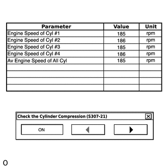
Monitor the engine speed (Engine Speed of Cyl #1 to #4) displayed on the GTS.
Tip:At first, the GTS displays extremely high cylinder engine speed values. After approximately 10 seconds of engine cranking, each cylinder engine speed measurement will change to the actual engine speed.
Note:Do not crank the engine continuously for 20 seconds or more.
If it is necessary to crank the engine again after Check the Cylinder Compression has been changed to ON and the engine has been cranked once, press Exit to return to the Active Test menu screen. Then change Check the Cylinder Compression to ON and crank the engine.
Use a fully-charged battery.
Stop cranking the engine, and then change "Check the Cylinder Compression" to OFF after the engine stops.
Note:If the Active Test is changed to OFF while the engine is being cranked, the engine will start.
Push the snapshot button to turn the snapshot function off.
Select "Stored Data" on the GTS screen, select the recorded data and display the data as a graph.
Tip:If the data is not displayed as a graph, the change of the values cannot be observed.
Check the change in engine speed values.
Tip:As the data values of the Active Test return to their default values when cranking is stopped, the engine speed value of each cylinder cannot be observed. Therefore, it is necessary to use the data recorded with the snapshot function to check the engine speed values recorded during cranking.
SYSTEM CHECK
Tip:Performing a System Check enables the system, which consists of multiple actuators, to be operated without removing any parts. In addition, it can show whether or not any DTCs are stored, and can detect potential malfunctions in the system. The System Check can be performed with the GTS.
Connect the GTS to the DLC3.
Turn the engine switch on (IG).
Turn the GTS on.
Enter the following menus: Powertrain / Engine and ECT / Utility
Perform the System Check by referring to the table below.
Tester Display
Test Part
Control Range
Diagnostic Note
Evaporative System Check
(Automatic Mode)
Perform 6 steps in order to operate EVAP key-off monitor automatically
35°C (95°F) or less
If no pending DTCs are output after performing this test, the system is functioning normally.
Refer to EVAP System Procedure.
Evaporative System Check
(Manual Mode)
Perform 6 steps in order to operate EVAP key-off monitor manually
35°C (95°F) or less
Used to detect malfunctioning parts.
Refer to EVAP System Procedure.
Reference Waveforms for Active Test
*4: Control the Injection Volume (Idling after warming up)
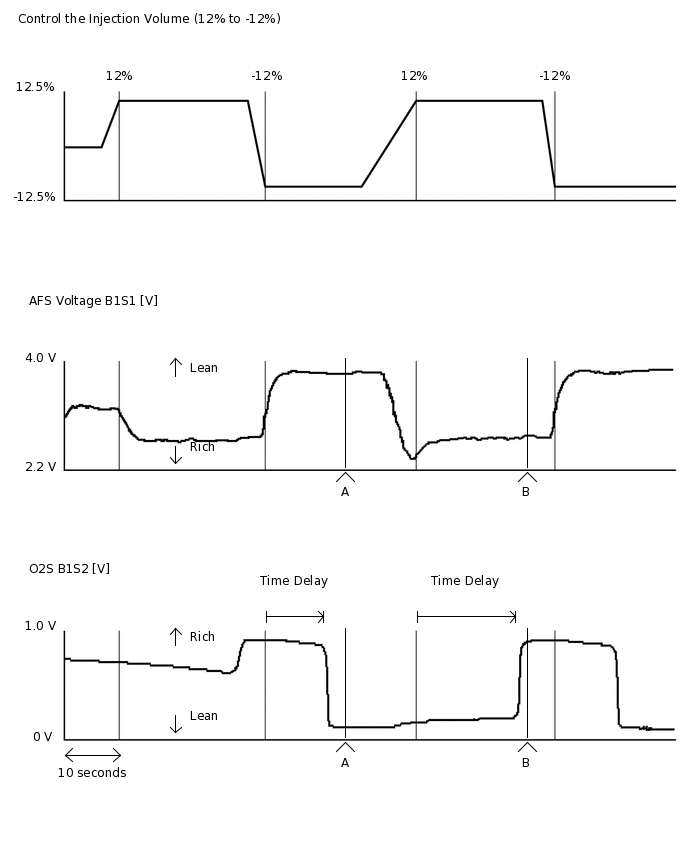 Tip:
Tip:During the Active Test, air fuel ratio feedback control and feedback learning are stopped.
Tester Display
Measurement Item/Range
Normal Condition
Control the Injection Volume
-
▲A
▲B
Active Test operation
-12%
12%
AFS Voltage B1S1
3.908 V
2.868 V
O2S B1S2
0.055 V
0.955 V
Tip:Usually, the value of AFS Voltage drops below 3.1 V when the control value for Control the Injection Volume is changed to 12%.
Usually, the value of AFS Voltage changes to 3.4 V or higher when the control value for Control the Injection Volume is changed to -12%.
Usually, the value of O2S changes to 0.55 V or higher when the control value for Control the Injection Volume is changed to 12%.
Usually, the value of O2S drops below 0.4 V when the control value for Control the Injection Volume is changed to -12%.
*5: Control the ETCS Open/Close Fast Speed [Active Test for electrical throttle control system] (Engine switch on (IG))
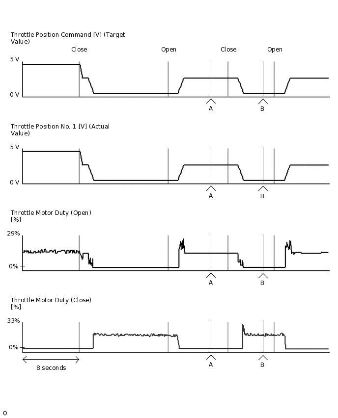 Tip:
Tip:Usually, Throttle Position Command (Target Value) and Throttle Position No. 1 (Actual Value) are almost the same.
If any DTCs related to the Electronic Throttle Control System (ETCS) are stored, this Active Test does not function.
Tester Display
Measurement Item/Range
Normal Condition
Control the ETCS Open/Close Fast Speed
-
▲A
▲B
Active Test operation
Open
Close
Throttle Position Command
2.597 V
0.742 V
Throttle Position No. 1
2.597 V
0.742 V
Throttle Motor Duty (Open)
11%
0%
Throttle Motor Duty (Close)
0%
12%
*6: Activate the VSV for Evap Control (Idling after warming up)
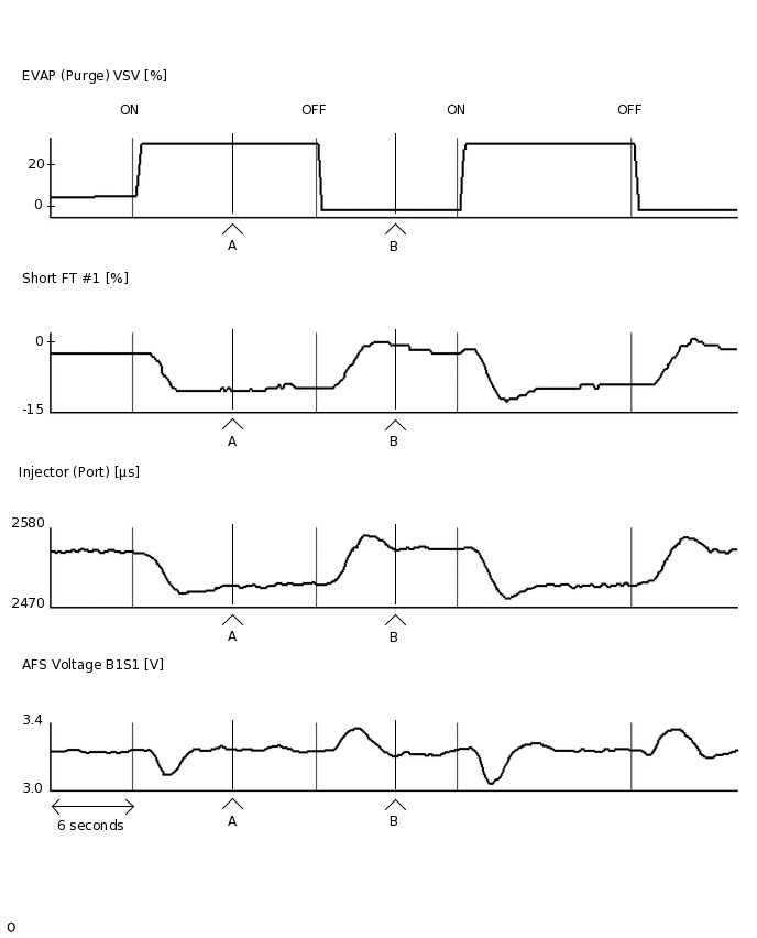 Tip:
Tip:Even when the Active Test is turned on (the purge VSV is opened 30%), air fuel ratio feedback continues and control is performed so that the air fuel ratio is the stoichiometric ratio. Therefore, by observing the change in "Short FT #1", it is possible to determine whether the purge VSV is actually open as well as the concentration of HC in the purge gas.
Tester Display
Measurement Item/Range
Normal Condition
Activate the VSV for Evap Control
-
▲A
▲B
Active Test operation
ON
OFF
EVAP (Purge) VSV
29.8%
0%
Short FT #1
-9.375%
0.000%
Injection (Port)
2495 μs
2541 μs
AFS Voltage B1S1
3.249 V
3.205 V
Tip:The graphs and values above are for reference only because the fuel injection volume (compensation volume) varies depending on the HC density of the purge air from the canister.
*7: Control the VVT Linear (Bank 1)
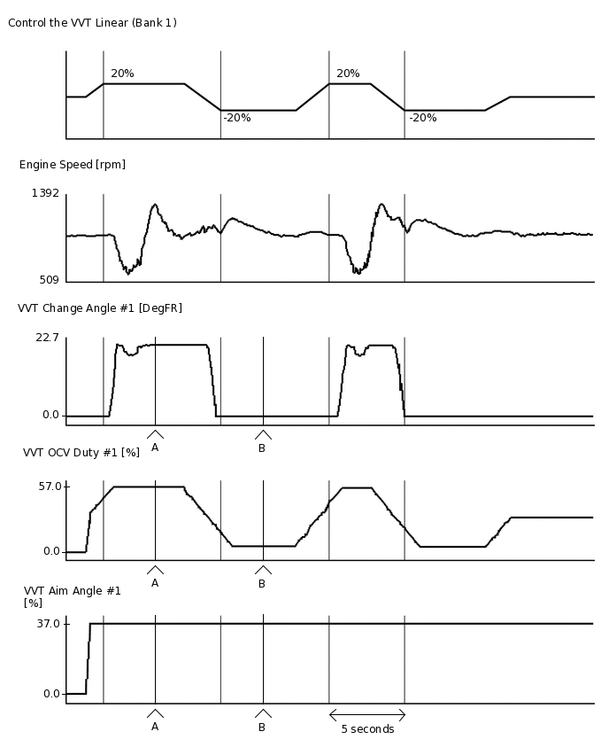
Tester Display
Measurement Item/Range
Normal Condition
Control the VVT Linear (Bank 1)
-
▲A
▲B
Active Test operation*
20%
-20%
VVT Change Angle #1
22.7 DegFR
0.0 DegFR
VVT OCV Duty #1
57.0%
17.0%
VVT Aim Angle #1
37.0%
37.0%
Tip:*: Change the control value for Control the VVT Linear to 20% or -20%.
The Control the VVT Linear Active Test considers the value of VVT Aim Angle to be 0 and raises or lowers the duty ratio with respect to VVT Aim Angle #1.
The sum of the control value for the Control the VVT Linear Active Test and the value of VVT Aim Angle is approximately equal to the value of VVT OCV Duty #1.
When the control value for the Control the VVT Linear Active Test is changed a few times, there should not be a large discrepancy between VVT OCV Duty when the system starts advancing or retarding the timing and the rate of change of VVT Change Angle #1.
*8: Control the VVT Exhaust Linear (Bank 1)
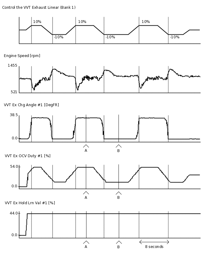
Tester Display
Measurement Item/Range
Normal Condition
Control the VVT Exhaust Linear (Bank 1)
-
▲A
▲B
Active Test operation*
10%
-10%
VVT Ex Chg Angle #1
38.5 DegFR
0.0 DegFR
VVT Ex OCV Duty #1
54.0%
34.0%
VVT Ex Hold Lrn Val #1
44.0%
44.0%
Tip:*: Change the control value for Control the VVT Exhaust Linear to 10% or -10%.
The Control the VVT Exhaust Linear Active Test considers the value of VVT Ex Hold Lrn Val to be 0 and raises or lowers the duty ratio with respect to VVT Ex Hold Lrn Val #1.
The sum of the control value for the Control the VVT Exhaust Linear Active Test and the value of VVT Ex Hold Lrn Val is approximately equal to the value of VVT Ex OCV Duty #1.
When the control value for the Control the VVT Exhaust Linear Active Test is changed a few times, there should not be a large discrepancy between VVT Ex OCV Duty when the system starts advancing or retarding the timing and the rate of change of VVT Ex Chg Angle #1.