OIL PUMP REMOVAL

CAUTION / NOTICE / HINT
Note
-
When replacing the injectors (including shuffling the injectors between the cylinders), common rail, intake manifold or cylinder head, it is necessary to replace the injection pipes with new ones.
-
When replacing the fuel supply pump, common rail, intake manifold or cylinder head, it is necessary to replace the fuel inlet pipe with a new one.
PROCEDURE
-
REMOVE ENGINE ASSEMBLY
-
DISCONNECT ENGINE WIRE
-
Disconnect the connectors and detach the clamps securing the engine wire to the engine, remove the bracket bolts and disconnect the engine wire from the engine.
-
-
REMOVE GENERATOR ASSEMBLY
-
REMOVE VACUUM PUMP ASSEMBLY
-
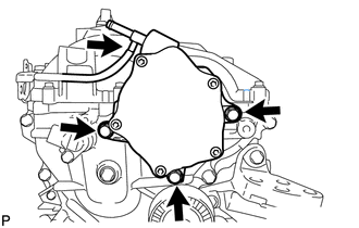
Disconnect the vacuum hose.
-
Remove the 3 bolts and vacuum pump.
-
Remove the 2 O-rings from the vacuum pump.
-
-
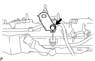
REMOVE IDLER PULLEY COVER PLATE
-
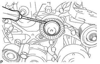
Text in Illustration *1 Tape Using a screwdriver, remove the idler pulley cover plate.
Tech Tips
Tape the screwdriver tip before use.
-
-
REMOVE NO. 1 IDLER PULLEY SUB-ASSEMBLY
-
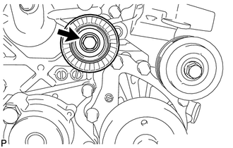
Remove the bolt and No. 1 idler pulley.
-
-
REMOVE NO. 2 IDLER PULLEY SUB-ASSEMBLY
-
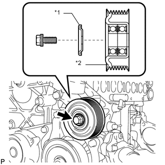
Text in Illustration *1 No. 2 Idler Pulley Cover Plate *2 No. 2 Idler Pulley Remove the bolt, No. 2 idler pulley cover plate and No. 2 idler pulley.
-
-
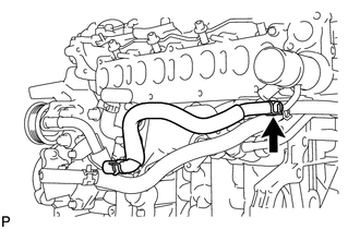
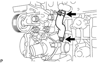
REMOVE NO. 4 WATER BY-PASS PIPE
-
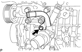
Remove the bolt and No. 4 water by-pass pipe from the water inlet housing.
-
Remove the O-ring from the No. 4 water by-pass pipe.
-
-
REMOVE ENGINE MOUNTING BRACKET
-
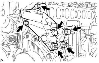
Remove the 4 bolts, 2 nuts and engine mounting bracket.
-
-
REMOVE V-RIBBED BELT TENSIONER ASSEMBLY
-
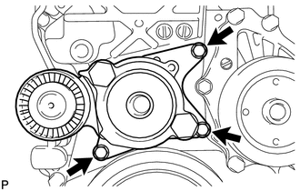
Remove the 3 bolts and V-ribbed belt tensioner.
Note
As the heads of the bolts are not as thick as those of typical bolts, be careful not to damage them during removal.
-
-
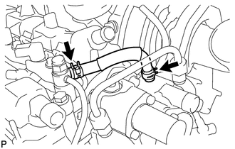
REMOVE DIESEL THROTTLE BODY ASSEMBLY
-
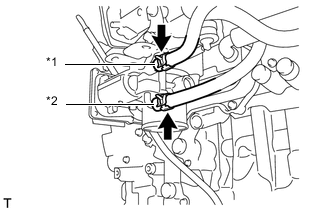
Text in Illustration *1 No. 6 Water By-pass Hose *2 No. 7 Water By-pass Hose Disconnect the No. 6 and No. 7 water by-pass hoses.
-
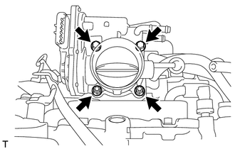
Remove the 2 bolts, 2 nuts, diesel throttle body and gasket.
-
-
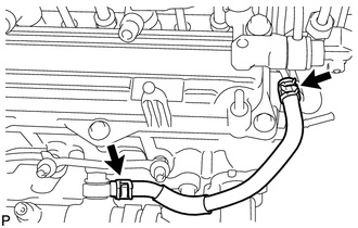
REMOVE NO. 7 WATER BY-PASS HOSE
-
DISCONNECT NO. 8 WATER BY-PASS HOSE
-
REMOVE EGR VALVE BRACKET
-
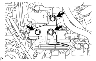
Remove the 3 bolts and 2 EGR valve brackets.
-
-
REMOVE NO. 2 EGR PIPE SUB-ASSEMBLY
-
REMOVE ELECTRIC EGR CONTROL VALVE ASSEMBLY
-
REMOVE ENGINE OIL LEVEL DIPSTICK GUIDE
-
Remove the engine oil level dipstick.
-
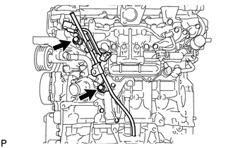
Remove the 2 bolts and engine oil level dipstick guide.
-
Remove the O-ring from the engine oil level dipstick guide.
-
-
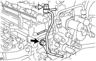
REMOVE FUEL INLET PIPE SUB-ASSEMBLY
-
REMOVE INJECTION PIPE SUB-ASSEMBLY
-
REMOVE NO. 4 FUEL HOSE
-
REMOVE COMMON RAIL ASSEMBLY
-
Remove the 2 bolts and common rail.
-
-
REMOVE INTAKE MANIFOLD INSULATOR
-
REMOVE DIESEL TURBO PRESSURE SENSOR
-
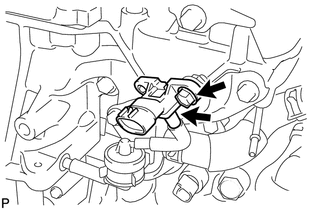
Disconnect the vacuum hose.
-
Remove the bolt and sensor.
-
-
REMOVE NO. 1 GAS FILTER
-
REMOVE GAS FILTER BRACKET
-
REMOVE ENGINE COVER BRACKET
-
REMOVE NO. 2 INTAKE MANIFOLD
-
REMOVE INTAKE MANIFOLD
-
REMOVE WATER BY-PASS HOSE
-
REMOVE OIL COOLER ASSEMBLY
-
REMOVE NO. 6 WATER BY-PASS HOSE
-
REMOVE NO. 8 WATER BY-PASS HOSE
-
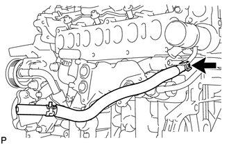
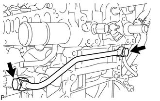
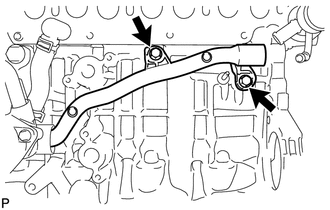
REMOVE NO. 3 WATER BY-PASS PIPE
-
Remove the 2 bolts and No. 3 water by-pass pipe.
-
Remove the O-ring from the No. 3 water by-pass pipe.
-
-
REMOVE NO. 1 TURBO OIL PIPE
-
Remove the 2 union bolts, 2 gaskets and No. 1 turbo oil pipe.
-
-
REMOVE NO. 1 OIL COOLER BRACKET
-
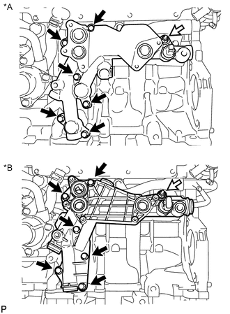
Text in Illustration *A for CCo *B for DPF 
Nut Remove the 6 bolts, nut and No. 1 oil cooler bracket.
-
for CCo:
Remove the 3 O-rings from the No. 1 oil cooler bracket.
-
for DPF:
Remove the 3 gaskets from the No. 1 oil cooler bracket.
-
-
REMOVE NO. 1 CYLINDER BLOCK INSULATOR
-
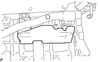
Remove the No. 1 cylinder block insulator from the cylinder block.
-
-
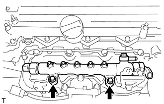
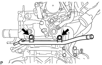
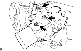
REMOVE NO. 2 WATER BY-PASS PIPE
-
Remove the 2 bolts and No. 2 water by-pass pipe from the water inlet housing.
-
Remove the O-ring from the No. 2 water by-pass pipe.
-
-
REMOVE NO. 4 WATER BY-PASS HOSE
-
REMOVE WATER INLET HOUSING
-
Remove the 3 nuts and water inlet housing.
-
Remove the gasket from the water inlet housing.
-
-
REMOVE NO. 2 FUEL PIPE (for CCo)
-
REMOVE FUEL HOSE PROTECTOR (for DPF)
-
REMOVE FUEL TUBE SUB-ASSEMBLY (for DPF)
-
REMOVE NO. 3 FUEL HOSE
-
REMOVE NO. 2 NOZZLE LEAKAGE PIPE
-
Remove the check valve and gasket.
Text in Illustration Check Valve -
Remove the bolt and No. 2 nozzle leakage pipe.
-
-
REMOVE NO. 1 NOZZLE LEAKAGE PIPE
-
REMOVE NO. 1 NOZZLE HOLDER CLAMP
-
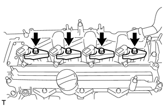
Remove the 4 bolts, 4 washers and 4 nozzle holder clamps.
-
-
REMOVE INJECTOR ASSEMBLY
-
REMOVE VACUUM REGULATING VALVE ASSEMBLY (for CCo)
-
REMOVE NO. 1 VACUUM SWITCHING VALVE ASSEMBLY
-
REMOVE VACUUM TRANSMITTING HOSE ASSEMBLY
-
for CCo:
Detach the 10 clamps and remove the 2 vacuum transmitting hoses.
-
for DPF:
Detach the 8 clamps and remove the 2 vacuum transmitting hoses.
-
-
REMOVE NO. 1 WIRING HARNESS CLAMP BRACKET (for DPF)
-
Remove the bolt and No. 1 wiring harness clamp bracket.
-
-
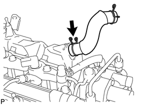
REMOVE VENTILATION HOSE
-
REMOVE OIL FILLER CAP SUB-ASSEMBLY
-
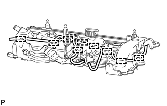
REMOVE CYLINDER HEAD COVER SUB-ASSEMBLY
-
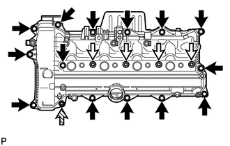
Remove the 4 nozzle holder clamp seats, 14 bolts, nut and cylinder head cover.
Text in Illustration 
Bolt Nozzle Holder Clamp Seat 
Nut -
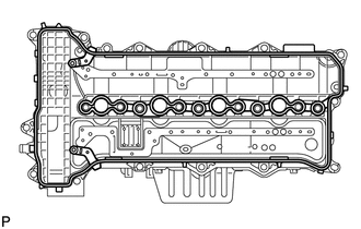
Remove the cylinder head cover gasket from the cylinder head cover.
-
-
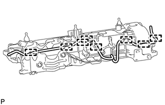
REMOVE NO. 2 OIL PAN SUB-ASSEMBLY
-
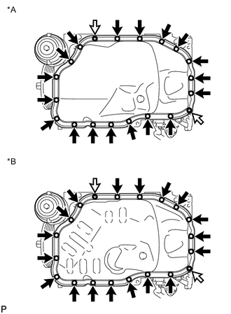
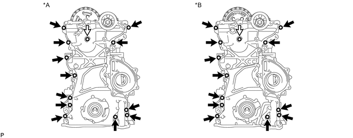
Text in Illustration *A for CCo *B for DPF Nut Remove the 18 bolts and 2 nuts.
-
Insert the blade of an oil pan seal cutter between the No. 2 oil pan and cylinder block, cut through the applied sealer and remove the No. 2 oil pan.
Note
-
Do not use the oil pan seal cutter for the area between the oil pan and timing chain cover.
-
Be careful not to damage the contact surfaces of the No. 2 oil pan.
-
-
-
REMOVE OIL FILTER ELEMENT
-
REMOVE OIL PRESSURE SWITCHING VALVE ASSEMBLY (for DPF)
-
REMOVE OIL FILTER BRACKET
-
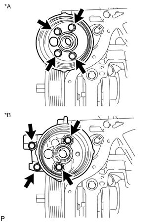
Text in Illustration *A for CCo *B for DPF Remove the 4 bolts and oil filter bracket.
-
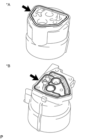
Text in Illustration *A for CCo *B for DPF Remove the gasket from the oil filter bracket.
-
-
REMOVE OIL CHECK VALVE SUB-ASSEMBLY (for DPF)
-
Using a 5 mm hexagon wrench, remove the bolt and oil check valve from the oil filter bracket.
-
-
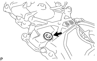
INSPECT OIL CHECK VALVE SUB-ASSEMBLY (for DPF)
-
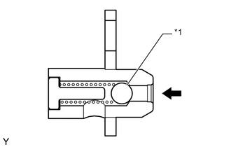
Text in Illustration *1 Ball Push the ball of the oil check valve to check if it is stuck.
If the check valve is stuck, replace the oil check valve sub-assembly.
-
-
REMOVE OIL STRAINER SUB-ASSEMBLY
-
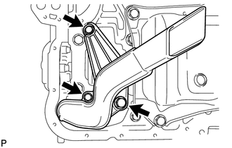
Remove the 3 bolts and oil strainer.
-
Remove the O-ring from the oil strainer.
-
-
REMOVE CAMSHAFT POSITION SENSOR
-
DISCONNECT CRANKSHAFT POSITION SENSOR WIRE HARNESS
-
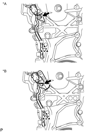
Text in Illustration *A for CCo *B for DPF Using a clip remover, remove the clip.
-
Remove the bolt and disconnect the crankshaft position sensor wire harness.
-
-
REMOVE WATER PUMP ASSEMBLY
-
REMOVE CRANKSHAFT PULLEY
-
REMOVE TIMING CHAIN COVER SUB-ASSEMBLY
-
Remove the 13 bolts and seal washer.
Text in Illustration *A for CCo *B for DPF Bolt and Seal Washer - - -
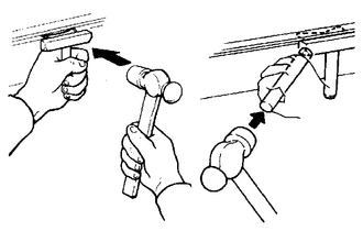
Remove the timing chain cover by prying between the timing chain cover and cylinder head, camshaft housing, cylinder block and stiffening crankcase with a screwdriver as shown in the illustration.
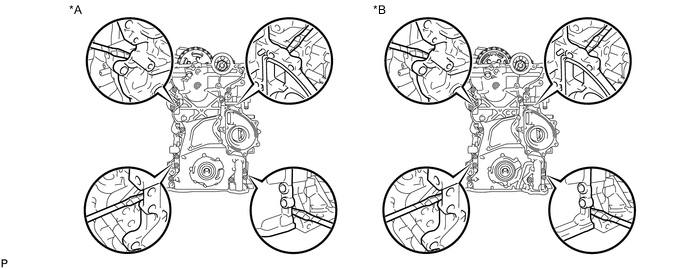
Text in Illustration *A for CCo *B for DPF Note
Be careful not to damage the contact surfaces of the cylinder head, camshaft housing, cylinder block, stiffening crankcase and chain cover.
Tech Tips
Tape the screwdriver tip before use.
-
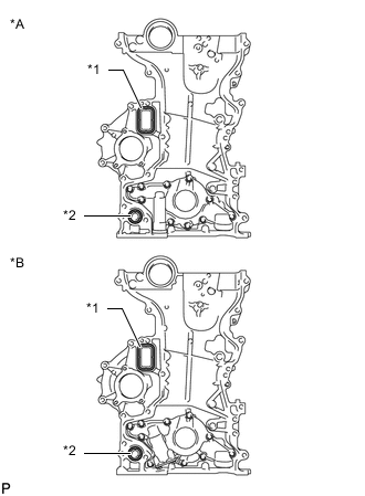
Text in Illustration *A for CCo *B for DPF *1 Gasket *2 O-Ring Remove the gasket and O-ring from the timing chain cover.
-
-
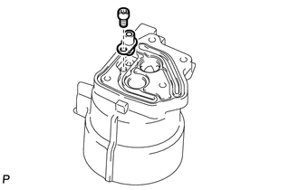
REMOVE STRAIGHT SCREW PLUG
Tech Tips
It is not necessary to replace the straight screw plug if there is no damage to the straight screw plug and no sign of oil leaks.
-
Using a 10 mm socket hexagon wrench, remove the straight screw plug and gasket.
-
-
REMOVE FRONT CRANKSHAFT OIL SEAL
-
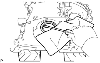
Place the timing chain cover on wooden blocks.
-
Using a screwdriver, pry out the oil seal.
Note
Do not damage the surface of the oil seal press fit hole.
Tech Tips
Tape the screwdriver tip before use.
-
-
REPLACE STUD BOLT
Tech Tips
If a stud bolt is deformed or its threads are damaged, replace it.
-
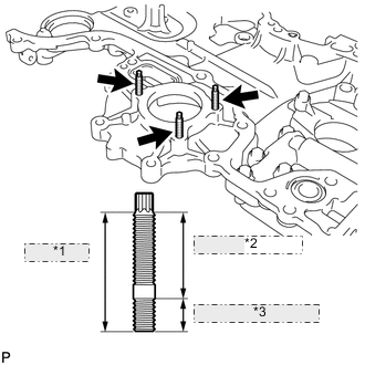
*1 34 mm (1.34 in.) *2 25 mm (0.984 in.) *3 9.0 mm (0.354 in.) Using an E6 "TORX" wrench, replace the 3 stud bolts.
- Torque:
- 3.0 N*m { 31 kgf*cm, 27 in.*lbf }
-