STOP AND START SYSTEM, Diagnostic DTC:P1540
| DTC Code | DTC Name |
|---|---|
| P1540 | Brake Booster Sensor Circuit (Open or Short) |
DESCRIPTION
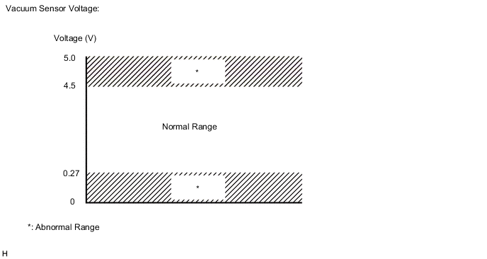
The engine stop and start ECU determines changes in the brake booster assembly pressure based on the voltage signal received from the vacuum sensor assembly in the brake booster assembly.
If the engine stop and start ECU judges that the signal received from the vacuum sensor assembly is abnormal, it stores DTC P1540 and blinks the stop and start cancel indicator light.
| DTC No. | DTC Detection Condition | Trouble Area |
|---|---|---|
| P1540 | The following conditions continue for 2 seconds or more (1 trip detection logic):
|
|
CONFIRMATION DRIVING PATTERN
Tech Tips
DTCs for the stop and start system are not cleared even if the malfunction has been repaired. After repairing the malfunction, be sure to clear the DTCs Click here.
-
CONFIRMATION AFTER TROUBLESHOOTING
-
Connect the GTS to the DLC3.
-
Turn the ignition switch to ON and turn the GTS on.
-
Clear the DTCs Click here.
-
Start the engine and allow it to idle for 15 seconds or more.
-
Stop the engine and turn the ignition switch to ON.
-
Turn the GTS on.
-
Enter the following menus: Powertrain / Stop and Start / Data List / Brake Boost Pressure.
-
While depressing the brake pedal several times, check that the Brake Boost Pressure value changes.
-
Check that DTCs are not output Click here.
-
-
STOP AND START SYSTEM OPERATION CHECK
Tech Tips
If the cable is disconnected from the negative (-) battery terminal, stop and start control is prohibited until refresh charge is completed. In this case, drive the vehicle approximately 5 to 40 minutes until refresh charge is completed and stop and start control operation is permitted.
-
Start the engine and warm it up.
-
Turn the air conditioning system off.
-
Drive the vehicle at 7 km/h (4.3 mph) or more.
CAUTION:
When performing the confirmation driving pattern, obey all speed limits and traffic laws.
-
Stop the vehicle, move the shift lever to neutral and release the clutch pedal.
-
Allow the engine to stop by stop and start control.
-
Depress the clutch pedal and start the engine.
-
WIRING DIAGRAM
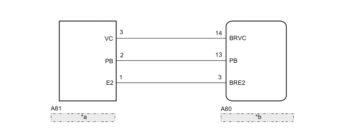
| *a | Vacuum Sensor Assembly |
| *b | Engine Stop and Start ECU |
CAUTION / NOTICE / HINT
Note
-
Before replacing the engine stop and start ECU, read the number of starter operations and write it into a new engine stop and start ECU Click here.
-
After replacing the engine stop and start ECU or air conditioning amplifier assembly, reset and perform learning of the air conditioning information in the engine stop and start ECU Click here.
-
After replacing the engine stop and start ECU or yaw rate sensor, perform deceleration sensor zero point clear and calibration Click here.
Tech Tips
Using the GTS, read the freeze frame data before troubleshooting. System condition information is recorded as freeze frame data the moment a DTC is stored. This information can be useful when troubleshooting Click here.
PROCEDURE
-
CHECK VACUUM SENSOR ASSEMBLY (PB TERMINAL VOLTAGE)
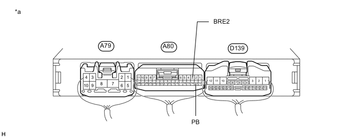
Text in Illustration *a Component with harness connected
(Engine Stop and Start ECU)
- -
-
Turn the ignition switch to ON.
-
Measure the voltage according to the value(s) in the table below.
Standard Voltage Tester Connection Switch Condition Result Proceed to A80-13 (PB) - A80-3 (BRE2) Ignition switch ON Voltage value is 4.7 V or higher or 0.6 V or lower A Voltage value is other than listed above B
B 
USE SIMULATION METHOD TO CHECK Click here
A 
-
-
CHECK HARNESS AND CONNECTOR (ENGINE STOP AND START ECU - VACUUM SENSOR ASSEMBLY)
-
Disconnect the A80 engine stop and start ECU connector.
-
Disconnect the A81 vacuum sensor assembly connector.
-
Measure the resistance according to the value(s) in the table below.
Standard Resistance Tester Connection Condition Specified Condition A80-13 (PB) - A81-2 (PB) Always Below 1 Ω A80-14 (BRVC) - A81-3 (VC) Always Below 1 Ω A80-3 (BRE2) - A81-1 (E2) Always Below 1 Ω A80-13 (PB) - Body ground Always 10 kΩ or higher A80-14 (BRVC) - Body ground Always 10 kΩ or higher A80-3 (BRE2) - Body ground Always 10 kΩ or higher A81-2 (PB) - Body ground Always 10 kΩ or higher A81-3 (VC) - Body ground Always 10 kΩ or higher A81-1 (E2) - Body ground Always 10 kΩ or higher
NG
REPAIR OR REPLACE HARNESS OR CONNECTOR
OK
-
-
CHECK ENGINE STOP AND START ECU (BRVC TERMINAL VOLTAGE)
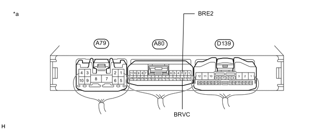
Text in Illustration *a Component with harness connected
(Engine Stop and Start ECU)
- -
-
Turn the ignition switch to ON.
-
Measure the voltage according to the value(s) in the table below.
Standard Voltage Tester Connection Switch Condition Specified Condition A80-14 (BRVC) - A80-3 (BRE2) Ignition switch ON 4.75 to 5.25 V
NG
REPLACE ENGINE STOP AND START ECU Click here
OK
-
-
REPLACE VACUUM SENSOR ASSEMBLY
-
Replace the vacuum sensor assembly Click here.
NEXT
-
-
CHECK DTC OUTPUT
-
Connect the GTS to the DLC3.
-
Turn the ignition switch to ON.
-
Turn the GTS on.
-
Enter the following menus: Powertrain / Stop and Start / Trouble Codes.
-
Check that no DTCs are output.
Result Result Proceed to DTCs are not output A DTC P1540 is output B
A
END
B
REPLACE ENGINE STOP AND START ECU Click here
-