LIGHTING SYSTEM Door Courtesy Switch Circuit
| DTC Code | DTC Name |
|---|---|
| Door Courtesy Switch Circuit |
DESCRIPTION
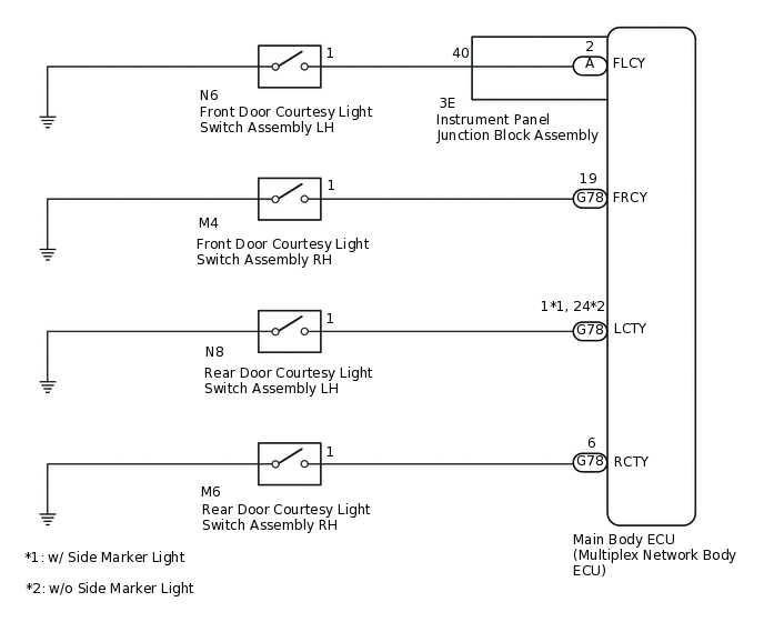
The main body ECU (multiplex network body ECU) receives a door open or closed signal from each door courtesy light switch.
WIRING DIAGRAM
CAUTION / NOTICE / HINT
When replacing the main body ECU (multiplex network body ECU), make sure to replace it with a new one.
PROCEDURE
READ VALUE USING GTS (DOOR COURTESY LIGHT SWITCH)
Using the GTS, read the Data List.
Body Electrical > Main Body > Data List
Tester Display
Measurement Item
Range
Normal Condition
Diagnostic Note
RR Door Courtesy SW
Rear door courtesy light switch RH signal
ON or OFF
ON: Rear door RH open
OFF: Rear door RH closed
-
RL Door Courtesy SW
Rear door courtesy light switch LH signal
ON or OFF
ON: Rear door LH open
OFF: Rear door LH closed
-
FR Door Courtesy SW
Front door courtesy light switch RH signal
ON or OFF
ON: Front door RH open
OFF: Front door RH closed
-
FL Door Courtesy SW
Front door courtesy light switch LH signal
ON or OFF
ON: Front door LH open
OFF: Front door LH closed
-
Body Electrical > Main Body > Data List
Tester Display
RR Door Courtesy SW
RL Door Courtesy SW
FR Door Courtesy SW
FL Door Courtesy SW
OK
Normal conditions listed above are displayed.
Result
Result
Proceed to
OK
A
NG (Front door courtesy light switch assembly RH does not operate)
B
NG (Front door courtesy light switch assembly LH does not operate)
C
NG (Rear door courtesy light switch assembly RH does not operate)
D
NG (Rear door courtesy light switch assembly LH does not operate)
E
C INSPECT FRONT DOOR COURTESY LIGHT SWITCH ASSEMBLY LHClick here
D INSPECT REAR DOOR COURTESY LIGHT SWITCH ASSEMBLY RHClick here
E INSPECT REAR DOOR COURTESY LIGHT SWITCH ASSEMBLY LHClick here
INSPECT FRONT DOOR COURTESY LIGHT SWITCH ASSEMBLY RH
Remove the front door courtesy light switch assembly RH.
Inspect the front door courtesy light switch assembly RH.
Result
Proceed to
OK
NG
CHECK HARNESS AND CONNECTOR (FRONT DOOR COURTESY LIGHT SWITCH ASSEMBLY RH - MAIN BODY ECU)
Disconnect the M4 front door courtesy light switch assembly RH connector.
Disconnect the G78 main body ECU (multiplex network body ECU) connector.
Measure the resistance according to the value(s) in the table below.
Standard Resistance
Tester Connection
Condition
Specified Condition
M4-1 - G78-19 (FRCY)
Always
Below 1 Ω
M4-1 - Body ground
Always
10 kΩ or higher
Result
Proceed to
OK
NG
NG REPAIR OR REPLACE HARNESS OR CONNECTOR
INSPECT FRONT DOOR COURTESY LIGHT SWITCH ASSEMBLY LH
Remove the front door courtesy light switch assembly LH.
Inspect the front door courtesy light switch assembly LH.
Result
Proceed to
OK
NG
CHECK HARNESS AND CONNECTOR (FRONT DOOR COURTESY LIGHT SWITCH ASSEMBLY LH - INSTRUMENT PANEL JUNCTION BLOCK ASSEMBLY)
Disconnect the N6 front door courtesy light switch assembly LH connector.
Disconnect the 3E instrument panel junction block assembly connector.
Measure the resistance according to the value(s) in the table below.
Standard Resistance
Tester Connection
Condition
Specified Condition
N6-1 - 3E-40 (FLCY)
Always
Below 1 Ω
N6-1 - Body ground
Always
10 kΩ or higher
Result
Proceed to
OK
NG
NG REPAIR OR REPLACE HARNESS OR CONNECTOR
INSPECT INSTRUMENT PANEL JUNCTION BLOCK ASSEMBLY
-
Remove the instrument panel junction block assembly.
for LHD:
for RHD:
Remove the main body ECU (multiplex network body ECU) from the instrument panel junction block assembly.
for LHD:
for RHD:
Measure the resistance according to the value(s) in the table below.
Standard Resistance
Tester Connection
Condition
Specified Condition
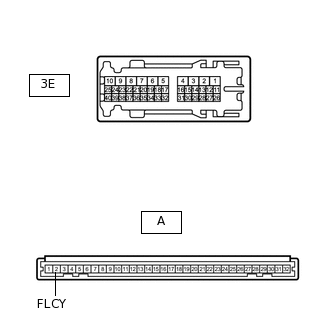
A-2 (FLCY) - 3E-40
Always
Below 1 Ω
Result
Proceed to
OK
NG
-
INSPECT REAR DOOR COURTESY LIGHT SWITCH ASSEMBLY RH
Remove the rear door courtesy light switch assembly RH.
Inspect the rear door courtesy light switch assembly RH.
Result
Proceed to
OK
NG
CHECK HARNESS AND CONNECTOR (REAR DOOR COURTESY LIGHT SWITCH ASSEMBLY RH - MAIN BODY ECU)
Disconnect the M6 rear door courtesy light switch assembly RH connector.
Disconnect the G78 main body ECU (multiplex network body ECU) connector.
Measure the resistance according to the value(s) in the table below.
Standard Resistance
Tester Connection
Condition
Specified Condition
M6-1 - G78-6 (RCTY)
Always
Below 1 Ω
M6-1 - Body ground
Always
10 kΩ or higher
Result
Proceed to
OK
NG
NG REPAIR OR REPLACE HARNESS OR CONNECTOR
INSPECT REAR DOOR COURTESY LIGHT SWITCH ASSEMBLY LH
Remove the rear door courtesy light switch assembly LH.
Inspect the rear door courtesy light switch assembly LH.
Result
Proceed to
OK
NG
CHECK HARNESS AND CONNECTOR (REAR DOOR COURTESY LIGHT SWITCH ASSEMBLY LH - MAIN BODY ECU)
Disconnect the N8 rear door courtesy light switch assembly LH connector.
Disconnect the G78 main body ECU (multiplex network body ECU) connector.
Measure the resistance according to the value(s) in the table below.
Standard Resistance
w/ Side Marker Light
Tester Connection
Condition
Specified Condition
N8-1 - G78-1 (LCTY)
Always
Below 1 Ω
N8-1 - Body ground
Always
10 kΩ or higher
w/o Side Marker Light
Tester Connection
Condition
Specified Condition
N8-1 - G78-24 (LCTY)
Always
Below 1 Ω
N8-1 - Body ground
Always
10 kΩ or higher
Result
Proceed to
OK
NG
NG REPAIR OR REPLACE HARNESS OR CONNECTOR