COMBUSTION TYPE POWER HEATER SYSTEM Power Heater Alternator Circuit
| DTC Code | DTC Name |
|---|---|
| Power Heater Alternator Circuit |
DESCRIPTION
The heater assembly receives engine operation signals from the generator control ECU assembly. If this circuit is open, the heater assembly will determine that the engine operation signals indicate on. If this circuit is shorted, the heater assembly will determine that the engine operation signals indicate off and the heater assembly will not operate.
WIRING DIAGRAM
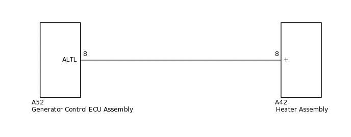
PROCEDURE
INSPECT GENERATOR ASSEMBLY
Inspect the generator assembly.
for 1AD-FTV:Click here
for 1ND-TV:Click here
Result
Proceed to
OK
NG
CHECK HARNESS AND CONNECTOR (HEATER ASSEMBLY - GENERATOR CONTROL ECU ASSEMBLY)
Disconnect the A42 heater assembly connector.
Measure the voltage according to the value(s) in the table below.
Standard Voltage
Tester Connection
Condition
Specified Condition
A42-8 (+) - Body ground
Engine is running (Generator assembly: Operating)
11 to 14 V
Result
Proceed to
OK
NG
CHECK HARNESS AND CONNECTOR (HEATER ASSEMBLY - GENERATOR CONTROL ECU ASSEMBLY)
Disconnect the A52 generator control ECU assembly connector.
Measure the resistance according to the value(s) in the table below.
Standard Resistance
Tester Connection
Condition
Specified Condition
A42-8 (+) - A52-8 (ALTL)
Always
Below 1 Ω
A42-8 (+) - Body ground
Always
10 kΩ or higher
Result
Proceed to
OK
NG
NG REPAIR OR REPLACE HARNESS OR CONNECTOR