CHARGING SYSTEM, Diagnostic DTC:P1550,P1551 and P1552
| DTC Code | DTC Name |
|---|---|
| P1550 | Battery Current Sensor Circuit |
| P1551 | Battery Current Sensor Circuit Low |
| P1552 | Battery Current Sensor Circuit High |
DESCRIPTION
The battery current sensor assembly detects the battery charge and discharge current amount. The battery current sensor assembly changes this information into a voltage signal and outputs it to the ECM. Based on this signal, the ECM sends power generation voltage commands to the generator.
DTC Code |
DTC Detection Condition |
Trouble Area |
|---|---|---|
P1550 |
When the ignition switch is ON, the difference between the maximum and minimum current values is below 1 A for 10 seconds or more (1 trip detection logic). |
|
P1551 |
When the ignition switch is ON, the battery current sensor output is below 0.2 V for 0.5 seconds or more (1 trip detection logic). |
|
P1552 |
When the ignition switch is ON, the battery current sensor output is higher than 4.8 V for 0.5 seconds or more (1 trip detection logic). |
|
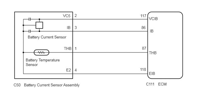
WIRING DIAGRAM
PROCEDURE
CHECK FOR DTC
Connect the GTS to the DLC3.
Start the engine.
Turn the GTS on.
Check for DTCs (Click here).
Table 1. Result Result
Proceed to
DTC P1550, P1551 or P1552 is output.
A
DTCs other than P1550, P1551 and P1552 are output.
B
READ VALUE USING GTS (BATTERY CURRENT)
Connect the GTS to the DLC3.
Turn the ignition switch to ON and turn off all electrical devices (headlights, blower motor, wiper, rear defogger, etc.).
Turn the GTS on.
Enter the following menus: Powertrain / Engine and ECT / Data List.
Check the values by referring to the table below.
Table 2. Charging Control Tester Display
Measurement Item/Range
Normal Condition
Diagnostic Note
Battery Current
Battery current / -125.0 to 124.9 A
Changes in response to generator power generation amount after engine warmed up while vehicle driven
-
Table 3. Result Result
Proceed to
Current value displayed on GTS is fixed at 0 A and does not change, or only changes by 1 A or less between -125 and 124.9 A.
A
Current value displayed on GTS changes between -20 and 0 A.
B
INSPECT BATTERY CURRENT SENSOR ASSEMBLY
Inspect the battery current sensor assembly (Click here).
CHECK HARNESS AND CONNECTOR (BATTERY CURRENT SENSOR ASSEMBLY - ECM)
Disconnect the C111 ECM connector.
Disconnect the C50 battery current sensor assembly connector.
Measure the resistance according to the value(s) in the table below.
Standard Resistance
Tester Connection
Condition
Specified Condition
C111-117 (VCIB) - C50-2 (VC5)
Always
Below 1 Ω
C111-118 (EIB) - C50-4 (E2)
C111-86 (IB) - C50-3 (IB)
C111-117 (VCIB) or C50-2 (VC5) - Body ground
Always
10 kΩ or higher
C111-118 (EIB) or C50-4 (E2) - Body ground
C111-86 (IB) or C50-3 (IB) - Body ground
REPAIR OR REPLACE HARNESS OR CONNECTOR