FRONT AXLE HUB(for 2WD) INSTALLATION

CAUTION / NOTICE / HINT
Tech Tips
-
Use the same procedureis for the Rh and LH side.
-
The following procedure is for the LH side.
PROCEDURE
-
INSTALL DISC BRAKE AIR GUIDE PLATE
-
Install disc brake air guide plate to the steering knuckle LH.
-
-
INSTALL FRONT AXLE HUB SUB-ASSEMBLY LH
-
Using a hexagon socket wrench 12 mm, install the front axle hub sub-assembly LH with the 4 bolts.
- Torque:
- 80 N*m { 816 kgf*cm, 59 ft.*lbf }
-
-
CONNECT STEERING KNUCKLE LH
-
TEMPORARILY TIGHTEN LOWER NO. 2 SUSPENSION ARM ASSEMBLY LH
-
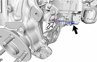
Insert the bolt from the back of the vehicle. Then temporarily tighten the lower No. 2 suspension arm assembly LH with the nut.
-
-
TEMPORARILY TIGHTEN FRONT PNEUMATIC CYLINDER ASSEMBLY WITH SHOCK ABSORBER LH (w/ Air Suspension)
-
TEMPORARILY TIGHTEN FRONT SHOCK ABSORBER ASSEMBLY LH (w/o Air Suspension)
-
CONNECT FRONT STABILIZER LINK ASSEMBLY LH
-
CONNECT FRONT HEIGHT CONTROL SENSOR SUB-ASSEMBLY LH
-
TEMPORARILY TIGHTEN FRONT LOWER SUSPENSION ARM ASSEMBLY LH
-
Temporarily tighten the front lower suspension arm assembly LH to the steering knuckle assembly LH with the nut.
-
-
CONNECT TIE ROD ASSEMBLY LH
-
INSTALL FRONT DISC BRAKE DUST COVER LH
-
Install the front disc brake dust cover LH with the 3 bolts.
- Torque:
- 8.0 N*m { 82 kgf*cm, 71 in.*lbf }
-
-
INSPECT FRONT AXLE HUB BEARING LOOSENESS
-
INSPECT FRONT AXLE HUB RUNOUT
-
INSTALL FRONT DISC LH
-
for 6-Pot Caliper
-
except 6-Pot Caliper
-
-
CONNECT DISC BRAKE CYLINDER ASSEMBLY
-
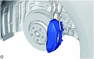
Temporarily install the 5 hub nuts to the front axle hub LH to secure the front disc LH.
Note
Do not apply excessive force to the flexible hose.
-
Temporarily install the disc brake cylinder assembly LH with the bolt on the lower side of the disc brake cylinder assembly LH.
-
Remove the SST.
-
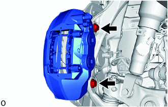
Install the disc brake cylinder assembly LH with the 2 bolts.
- Torque:
- 135 N*m { 1377 kgf*cm, 100 ft.*lbf }
-
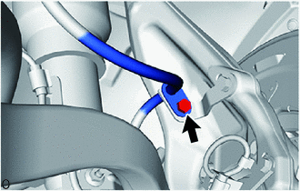
Install the front flexible hose bracket LH to the steering knuckle with the bolt.
- Torque:
- 21 N*m { 214 kgf*cm, 15 ft.*lbf }
-
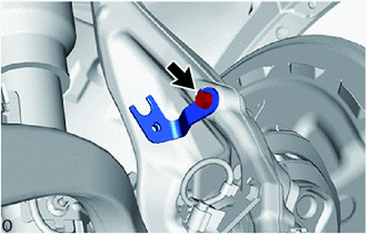
Connect the flexible hose to the front flexible hose bracket LH with the bolt.
- Torque:
- 20 N*m { 204 kgf*cm, 15 ft.*lbf }
-
for RH side:
-
Attach the guide to connect the pad wear indicator wire assembly.
-
-
-
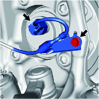
CONNECT FRONT SKID CONTROL SENSOR WIRE
-
for LH Side:
-
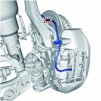
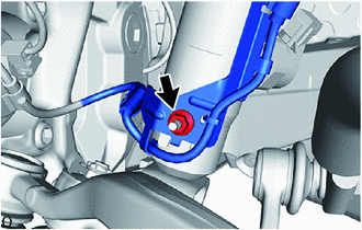
Install the sensor clamp with the bolt.
- Torque:
- 10 N*m { 102 kgf*cm, 7 ft.*lbf }
Note
Do not twist the skid control sensor wire when installing it.
-
Connect the skid control sensor wire connector.
-
-
for RH Side:
-
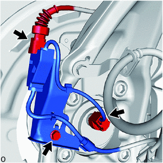
Install the sensor clamp with the bolt.
- Torque:
- 10 N*m { 102 kgf*cm, 7 ft.*lbf }
Note
Do not twist the skid control sensor wire when installing it.
-
Connect the skid control sensor wire connector.
-
Connect the pad wear indicator connector.
-
-
Install the sensor clamp with the nut.
- Torque:
- 8.5 N*m { 87 kgf*cm, 75 in.*lbf }
Note
Do not twist the skid control sensor wire when installing it.
-
-
STABILIZE SUSPENSION
-
FULLY TIGHTEN LOWER NO. 2 SUSPENSION ARM ASSEMBLY LH
-
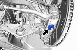
Tighten the installation bolt of the lower No. 2 suspension arm assembly LH.
- Torque:
- 130 N*m { 1326 kgf*cm, 96 ft.*lbf }
-
-
FULLY TIGHTEN FRONT LOWER SUSPENSION ARM ASSEMBLY LH
-
Tighten the installation nut of the steering knuckle assembly LH.
- Torque:
- 145 N*m { 1479 kgf*cm, 107 ft.*lbf }
Note
Further tighten the nut up to 60° if the holes for the clip are not aligned.
-
Install a new clip.
-
-
FULLY TIGHTEN FRONT SHOCK ABSORBER ASSEMBLY LH (w/o Air Suspension)
-
Fully tighten the front shock absorber assembly bolt.
- Torque:
- 110 N*m { 1122 kgf*cm, 81 ft.*lbf }
Note
Because the nut has its own stopper, do not turn the nut. Tighten the bolt with the nut secured.
-
-
FULLY TIGHTEN FRONT PNEUMATIC CYLINDER ASSEMBLY WITH SHOCK ABSORBER LH (w/ Air Suspension)
-
Fully tighten the front pneumatic cylinder assembly with shock absorber LH bolt.
- Torque:
- 110 N*m { 1122 kgf*cm, 81 ft.*lbf }
Note
Because the nut has its own stopper, do not turn the nut. Tighten the bolt with the nut secured.
-
-
INSTALL REAR LOWER ARM MOUNTING REINFORCEMENT SUB-ASSEMBLY LH
-
INSTALL ENGINE SIDE COVER LH
-
INSTALL NO. 2 ENGINE UNDER COVER ASSEMBLY
-
INSTALL FRONT WHEEL
-
CONNECT BRAKE BOOSTER PUMP CONNECTOR (w/o Vacuum Brake Booster)
-
CHECK FOR SPEED SENSOR SIGNAL
-
w/ Vacuum Brake Booster: Click here
-
w/o Vacuum Brake Booster: Click here
-
-
INSPECT AND ADJUST FRONT WHEEL ALIGNMENT
-
INSPECT AND ADJUST VEHICLE HEIGHT (w/ Air Suspension)
-
PERFORM INITIALIZATION
Parking support brake system Panoramic view monitor system Parking assist monitor system Automatic headlight beam level control system -
ADJUST HEADLIGHT AIMING