SFI SYSTEM(w/ EGR System), Diagnostic DTC:P0500
| DTC Code | DTC Name |
|---|---|
| P0500 | Vehicle Speed Sensor "A" |
DESCRIPTION
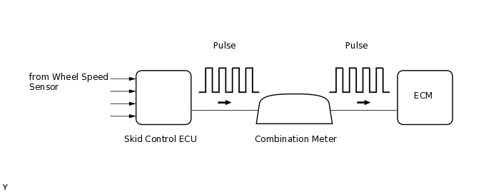
The speed sensor detects the wheel speed and sends the appropriate signals to the skid control ECU. The skid control ECU converts these wheel speed signals into a pulse signal and outputs it to the ECM via the combination meter. The ECM determines the vehicle speed based on the frequency of this pulse signal.
DTC No. |
Detection Item |
DTC Detection Condition |
Trouble Area |
Warning Indicate |
Memory |
|---|---|---|---|---|---|
P0500 |
Vehicle Speed Sensor "A" |
While the vehicle is being driven, no vehicle speed signal is transmitted to the ECM (2 trip detection logic). |
|
Comes on |
DTC stored |
MONITOR DESCRIPTION
The ECM assumes that the vehicle is being driven when the vehicle speed measured by the output speed sensor (SP2) is more than 9 km/h (5.6 mph). If there is no speed signal from the combination meter despite this condition being met, the ECM interprets this as a malfunction in the speed signal circuit. The ECM then illuminates the MIL and stores the DTC.
MONITOR STRATEGY
Required Sensors/Components (Main) |
Vehicle Speed Sensor, Combination meter assembly and Skid control ECU |
Required Sensors/Components (Related) |
Park/neutral position switch assembly, Output speed sensor (SP2) |
Frequency of Operation |
Continuous |
TYPICAL ENABLING CONDITIONS
Vehicle speed at output speed sensor (SP2) |
9 km/h (5.59 mph) or more |
TYPICAL MALFUNCTION THRESHOLDS
Vehicle speed sensor signal |
No pulse input |
CONFIRMATION DRIVING PATTERN
Connect the intelligent tester to the DLC3.
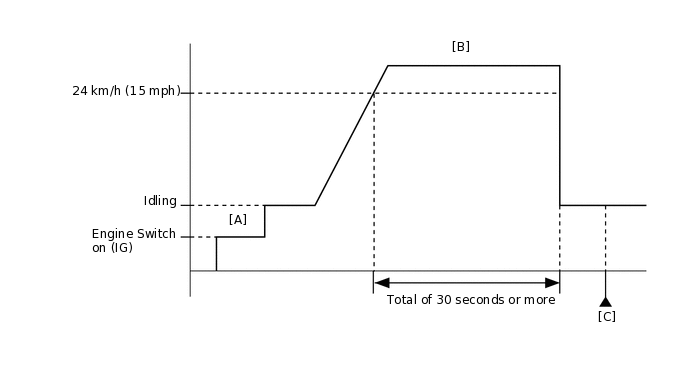
Turn the engine switch on (IG) and turn the tester on.
Clear DTCs (even if no DTCs are stored, perform the clear DTC operation).
Turn the engine switch off and wait for at least 30 seconds.
Turn the engine switch on (IG) and turn the tester on [A].
Start the engine.
Drive the vehicle at 24 km/h (15 mph) or more for a total of 30 seconds or more [B].
CAUTION:When performing the confirmation driving pattern, obey all speed limits and traffic laws.
Stop the vehicle.
Enter the following menus: Powertrain / Engine and ECT / DTC [C].
Read the pending DTCs.
Tip:If a pending DTC is output, the system is malfunctioning.
If a pending DTC is not output, perform the following procedure.
Enter the following menus: Powertrain / Engine and ECT / Utility / All Readiness.
Input the DTC: P0500.
Check the DTC judgment result.
Tester Display
Description
NORMAL
DTC judgment completed
System normal
ABNORMAL
DTC judgment completed
System abnormal
INCOMPLETE
DTC judgment not completed
Perform driving pattern after confirming DTC enabling conditions
N/A
Unable to perform DTC judgment
Number of DTCs which do not fulfill DTC preconditions has reached ECU memory limit
Tip:If the judgment result shows NORMAL, the system is normal.
If the judgment result shows ABNORMAL, the system has a malfunction.
WIRING DIAGRAM
CAUTION / NOTICE / HINT
Read freeze frame data using the intelligent tester. Freeze frame data records the engine condition when malfunctions are detected. When troubleshooting, freeze frame data can help determine if the vehicle was moving or stationary, if the engine was warmed up or not, if the air-fuel ratio was lean or rich, and other data from the time the malfunction occurred.
PROCEDURE
READ VALUE USING INTELLIGENT TESTER (VEHICLE SPEED)
Connect the intelligent tester to the DLC3.
Turn the engine switch on (IG).
Turn the tester on.
Enter the following menus: Powertrain / Engine and ECT / Data List / Vehicle Speed.
Powertrain > Engine and ECT > Data List
Tester Display
Vehicle Speed
Drive the vehicle.
Read the value displayed on the tester.
OK
Vehicle speeds displayed on tester and speedometer display are equal.
Result
Result
OK
NG
CHECK COMBINATION METER SYSTEM
Inspect the circuits that send vehicle speed signals to this system in the meter system.
During inspection for the meter section, if there is an instruction that indicates to go back to inspections for each system, proceed to the next step.
Result
Result
NEXT
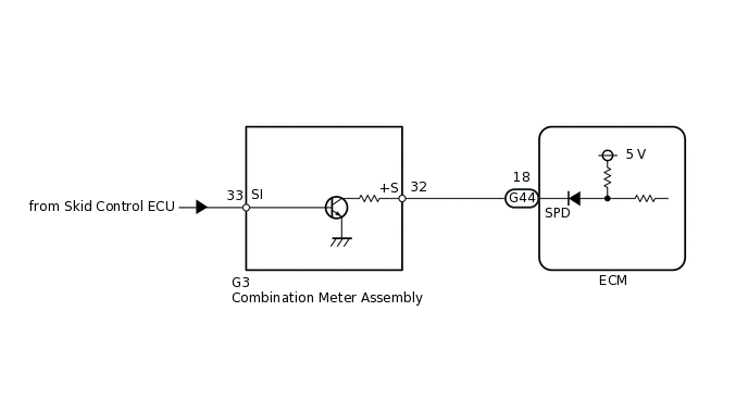
CHECK HARNESS AND CONNECTOR (ECM - COMBINATION METER)
Disconnect the ECM connector.
Disconnect the combination meter connector.
Measure the resistance according to the value(s) in the table below.
Standard Resistance
Tester Connection
Condition
Specified Condition
G3-32 (+S) - G44-18 (SPD)
Always
Below 1 Ω
Reconnect the ECM connector.
Reconnect the combination meter connector.
Result
Result
OK
NG
CHECK HARNESS AND CONNECTOR (ECM - NO. 4 JUNCTION BLOCK)
Disconnect the ECM connector.
Disconnect the No. 4 junction block connector.
Measure the resistance according to the value(s) in the table below.
Standard Resistance
Tester Connection
Condition
Specified Condition
4A-93 - G44-18 (SPD)
Always
Below 1 Ω
Reconnect the ECM connector.
Reconnect the No. 4 junction block connector.
Result
Result
OK
NG
OK REPAIR OR REPLACE NO. 4 JUNCTION BLOCK
NG REPAIR OR REPLACE HARNESS OR CONNECTOR