EGR VALVE REMOVAL
CAUTION / NOTICE / HINT
The necessary procedures (adjustment, calibration, initialization, or registration) that must be performed after parts are removed, installed, or replaced during the EGR valve removal/installation are shown below.
| Replacement Part or Procedure | Necessary Procedures | Effects/Inoperative when not Performed | Link |
|---|---|---|---|
| Replacement of diesel throttle body assembly | Perform initialization | - |
|
| Replacement of electric EGR control valve assembly | Perform initialization | - |
|
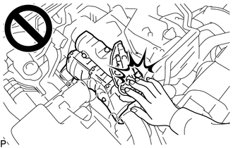
CAUTION:
To prevent burns, do not touch the engine, exhaust manifold or other high temperature components while the engine is hot.
PROCEDURE
-
DRAIN ENGINE COOLANT
-
REMOVE DIESEL THROTTLE BODY ASSEMBLY
-
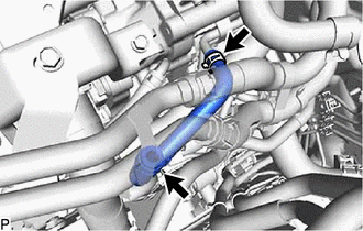
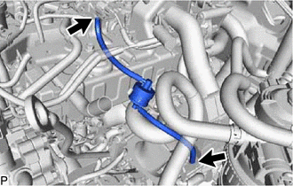
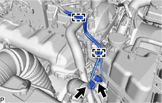
REMOVE NO. 2 WATER BY-PASS PIPE
CAUTION:
To prevent burns, do not touch the engine, exhaust manifold or other high temperature components while the engine is hot.
-
w/ Heater:
-
w/ DPF:
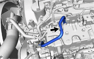
Slide the clamp and disconnect the No. 18 water by-pass hose from the EGR pipe with cooler sub-assembly.
-
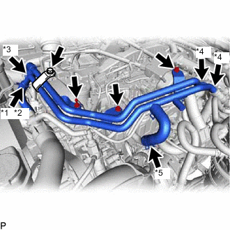
*1 Water Hose Sub-assembly *2 No. 13 Water By-pass Hose *3 No. 15 Water By-pass Hose *4 Heater Hose *5 No. 16 Water By-pass Hose w/ Viscous Heater:
Slide the clamp and disconnect the No. 2 water by-pass pipe from the water hose sub-assembly.
-
w/o Viscous Heater:
Slide the clamp and disconnect the No. 2 water by-pass pipe from the No. 13 water by-pass hose.
-
Slide the clamp and disconnect the No. 15 water by-pass hose from the water by-pass pipe.
-
Slide the 2 clamps and disconnect the 2 heater hoses from the No. 2 water by-pass pipe.
-
Slide the clamp and disconnect the No. 16 water by-pass hose from the No. 1 EGR cooler.
-
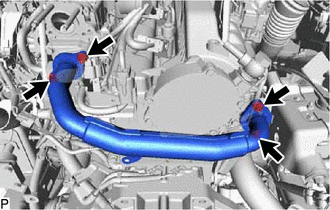
Remove the 4 bolts and No. 2 water by-pass pipe from the cylinder head cover sub-assembly, No. 3 water by-pass pipe sub-assembly and No. 2 engine cover bracket.
-
-
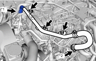
*1 No. 15 Water By-pass Hose *2 No. 16 Water By-pass Hose w/o Heater:
-
Slide the clamp and disconnect the No. 15 water by-pass hose from the water by-pass pipe.
-
Slide the clamp and disconnect the No. 16 water by-pass hose from the No. 1 EGR cooler.
-
Remove the 3 bolts and No. 2 water by-pass pipe from the cylinder head cover sub-assembly, No. 3 water by-pass pipe sub-assembly and No. 2 engine cover bracket.
-
-
-
REMOVE GAS FILTER
-
Disconnect the 2 vacuum hoses from the turbo pressure sensor and intake manifold.
-
Remove the gas filter from the gas filter bracket.
-
-
REMOVE TURBO PRESSURE SENSOR
-
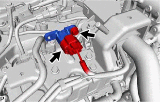
Disconnect the connector from the turbo pressure sensor.
-
Remove the bolt and turbo pressure sensor from the No. 3 water by-pass pipe sub-assembly.
-
-
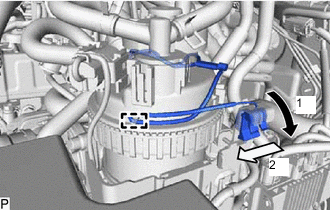
REMOVE NO. 2 HOSE TO HOSE TUBE
-
Slide the clamp to disconnect the union to connector tube hose from the No. 1 hose to hose tube.
-
Slide the clamp to disconnect the union to check valve hose from the vacuum pump assembly.
-
Remove the 2 bolts and No. 2 hose to hose tube from the cylinder head cover sub-assembly and hose bracket.
-
-
REMOVE NO. 2 ENGINE COVER BRACKET
-
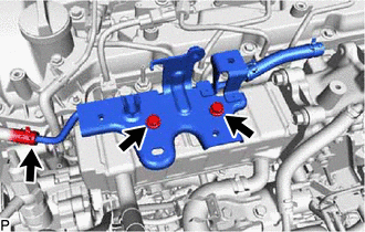
Remove the 2 bolts and No. 2 engine cover bracket from the No. 3 water by-pass pipe sub-assembly and No. 2 EGR valve assembly.
-
-
DISCONNECT FUEL FILTER ASSEMBLY
-
Disconnect the clamp and slide the lead wire as shown in the illustration to remove it.
-
Disconnect the fuel filter assembly from the fuel filter support.
-
-
DISCONNECT UREA TANK FILLER PIPE ASSEMBLY (w/ Urea SCR System)
-
Detach the claw and disconnect the urea tank filler pipe assembly from the No. 1 urea tank filler pipe support.
-
-
REMOVE NO. 1 UREA TANK FILLER PIPE SUPPORT (w/ Urea SCR System)
-
Remove the 2 bolts and No. 1 urea tank filler pipe support from the body.
-
-
DISCONNECT ENGINE WIRE
-
Detach the 2 clamps and disconnect the 2 connectors from the turbocharger sub-assembly.
-
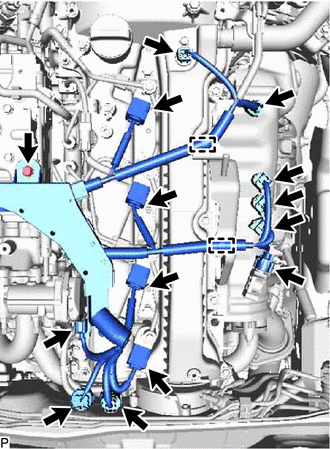
w/ DPF:
-
Disconnect the connector from the differential pressure sensor.
-
Disconnect the 3 connectors from the 3 exhaust gas temperature sensors
-
Disconnect the connector from the exhaust fuel addition injector assembly.
-
Disconnect the connector from the camshaft position sensor.
-
Disconnect the 4 connectors from the 4 injector assemblies.
-
Disconnect the connector from the electric EGR control valve assembly.
-
Disconnect the connector from the glow plug connector.
-
Disconnect the connector from the sensor wire of common rail assembly.
-
Detach the 2 clamps and remove the bolt.
-
-
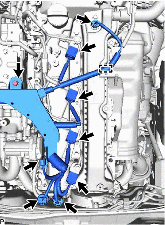
w/o DPF:
-
Disconnect the connector from the camshaft position sensor.
-
Disconnect the 4 connectors from the 4 injector assemblies.
-
Disconnect the connector from the electric EGR control valve assembly.
-
Disconnect the connector from the glow plug connector.
-
Disconnect the connector from the sensor wire of common rail assembly.
-
Detach the clamp and remove the bolt.
-
-
Detach the clamp and disconnect the connector from the power steering oil pressure switch.
-
Detach the clamp and remove the bolt.
-
Disconnect the connector from the vacuum control valve set.
-
-
REMOVE EGR VALVE BRACKET
CAUTION:
To prevent burns, do not touch the engine, exhaust manifold or other high temperature components while the engine is hot.
-
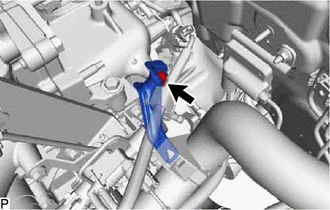
Remove the bolt, nut and EGR valve bracket from the electric EGR control valve assembly and intake manifold.
-
-
REMOVE NO. 2 EGR PIPE
CAUTION:
To prevent burns, do not touch the engine, exhaust manifold or other high temperature components while the engine is hot.
-
Remove the bolt, 4 nuts and No. 2 EGR pipe from the electric EGR control valve assembly and intake manifold.
-
Remove the 2 gaskets.
-
-
REMOVE ELECTRIC EGR CONTROL VALVE ASSEMBLY
CAUTION:
To prevent burns, do not touch the engine, exhaust manifold or other high temperature components while the engine is hot.
-
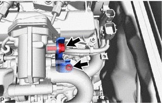
Detach the clamp and disconnect the connector from the common rail assembly.
-
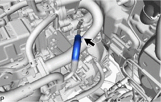
Slide the clamp and disconnect the No. 9 water by-pass hose from the electric EGR control valve assembly.
-
Remove the 2 bolts and electric EGR control valve assembly.
-
Remove the gasket.
-
-
REMOVE NO. 3 WATER BY-PASS PIPE SUB-ASSEMBLY
CAUTION:
To prevent burns, do not touch the engine, exhaust manifold or other high temperature components while the engine is hot.
-
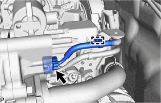
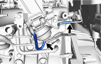
Disconnect the No. 4 fuel hose from the No. 3 water by-pass pipe sub-assembly.
-
Slide the clamp and disconnect the No. 8 water by-pass hose from the No. 3 water by-pass pipe sub-assembly.
-
Remove the 2 bolts and No. 3 water by-pass pipe sub-assembly from the No. 1 EGR cooler.
-
-
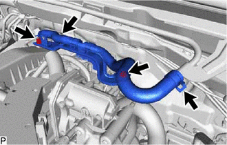
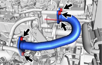
DISCONNECT NO. 4 WATER BY-PASS PIPE SUB-ASSEMBLY
CAUTION:
To prevent burns, do not touch the engine, exhaust manifold or other high temperature components while the engine is hot.
-
w/ DPF:
Slide the clamp and disconnect the No. 17 water by-pass hose from the No. 1 EGR pipe sub-assembly.
-
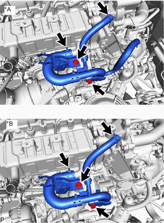
*A w/ DPF *B w/o DPF Slide the clamp and disconnect the No. 7 water by-pass hose from the No. 1 EGR cooler.
-
Slide the clamp and disconnect the water hose from the No. 2 EGR valve assembly.
-
Remove the 2 bolts and disconnect the No. 4 water by-pass pipe sub-assembly from the intake manifold.
-
-
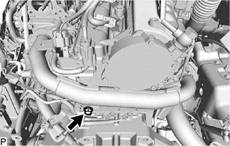
REMOVE EGR PIPE WITH COOLER SUB-ASSEMBLY (w/ DPF)
CAUTION:
To prevent burns, do not touch the engine, exhaust manifold or other high temperature components while the engine is hot.
-
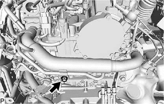
Remove the bolt and disconnect the EGR pipe with cooler sub-assembly from the vacuum transmitting pipe sub-assembly.
-
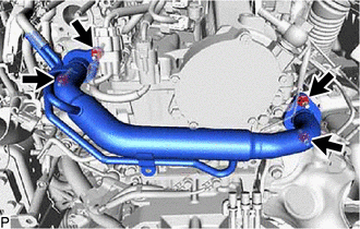
Remove the 4 nuts and the EGR pipe with cooler sub-assembly from the exhaust manifold and EGR valve adapter.
-
Remove the 2 gaskets.
-
Using an E8 "TORX" socket wrench, remove the 2 stud bolts from the exhaust manifold.
-
-
REMOVE NO. 1 EGR PIPE SUB-ASSEMBLY (w/o DPF)
CAUTION:
To prevent burns, do not touch the engine, exhaust manifold or other high temperature components while the engine is hot.
-
Remove the bolt and disconnect the No. 1 EGR pipe sub-assembly from the vacuum transmitting pipe sub-assembly.
-
Remove the 4 nuts and the No. 1 EGR pipe sub-assembly from the exhaust manifold and EGR valve adapter.
-
Remove the 2 gaskets.
-
Using an E8 "TORX" socket wrench, remove the 2 stud bolts from the exhaust manifold.
-
-
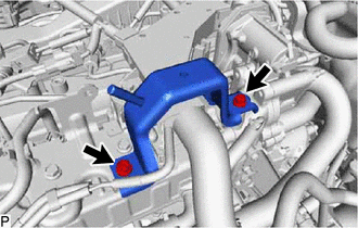
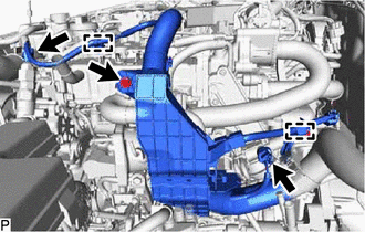
REMOVE VACUUM CONTROL VALVE SET
-
Remove the bolt and engine wire bracket.
-
Disconnect the 2 vacuum hoses from the No. 2 vacuum transmitting pipe sub-assembly and No. 2 EGR valve assembly.
-
Remove the 2 bolts and vacuum control valve set from the intake manifold.
-
-
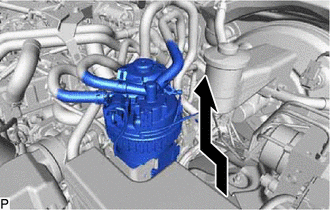
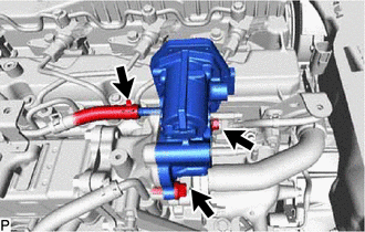
REMOVE NO. 1 EGR COOLER AND NO. 2 EGR VALVE ASSEMBLY
CAUTION:
To prevent burns, do not touch the engine, exhaust manifold or other high temperature components while the engine is hot.
-
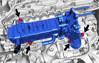
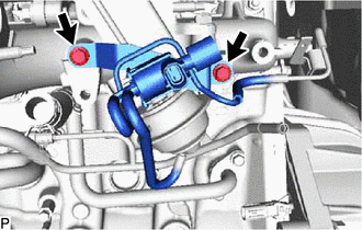
Remove the 4 bolts and No. 1 EGR cooler and No. 2 EGR valve assembly from the intake manifold.
-
-
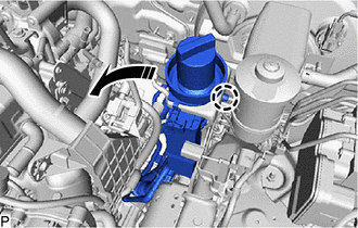
REMOVE EGR VALVE ADAPTER
-
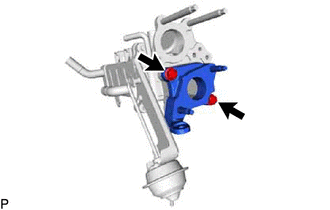
Remove the 2 bolts and EGR valve adapter from the No. 2 EGR valve assembly.
-
Remove the gasket.
-
-
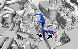
REMOVE NO. 2 EGR VALVE ASSEMBLY
-
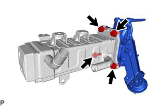
Remove the 4 bolts and No. 2 EGR valve assembly from the No. 1 EGR cooler.
-
Remove the gasket.
-
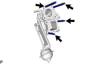
Using an E8 "TORX" socket wrench, remove the 4 stud bolts from the No. 2 EGR valve assembly.
-