METER / GAUGE SYSTEM, Diagnostic DTC:B1500
| DTC Code | DTC Name |
|---|---|
| B1500 | Fuel Sender Open Detected |
DESCRIPTION
This DTC is stored when the combination meter assembly detects a fuel sender gauge assembly malfunction.
DTC Code |
DTC Detection Condition |
Trouble Area |
|---|---|---|
B1500 |
The combination meter detects a fuel sender gauge assembly malfunction. |
|
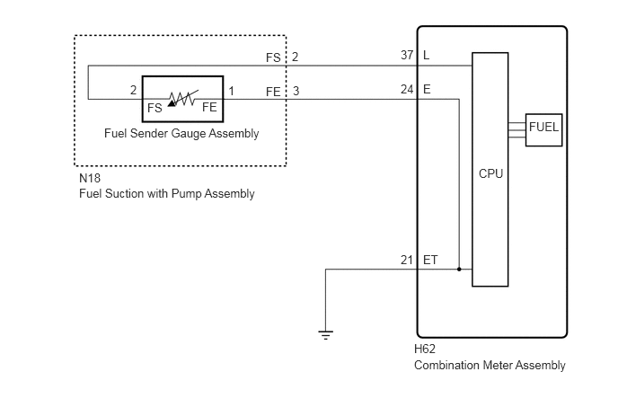
WIRING DIAGRAM
PROCEDURE
READ VALUE USING INTELLIGENT TESTER (FUEL SENDER GAUGE)
Use the Data List to check if the fuel receiver gauge is operating properly (Click here).
Table 1. Combination Meter Tester Display
Measurement Item/Range
Normal Condition
Diagnostic Note
Fuel Input
Fuel sender gauge input/Min.: 0, Max.: 127.5
Fuel sender gauge input value
Unit: L
OK
Fuel amount value displayed on the intelligent tester is almost the same as needle indication.
CHECK HARNESS AND CONNECTOR (COMBINATION METER ASSEMBLY - FUEL SUCTION WITH PUMP ASSEMBLY AND BODY GROUND)
Disconnect the H62 combination meter assembly connector.
Disconnect the N18 fuel suction with pump assembly connector.
Measure the resistance according to the value(s) in the table below.
Standard Resistance
Tester Connection
Condition
Specified Condition
H62-37 (L) - N18-2 (FS)
Always
Below 1 Ω
H62-24 (E) - N18-3 (FE)
Always
Below 1 Ω
H62-21 (ET) - Body ground
Always
Below 1 Ω
H62-37 (L) or N18-2 (FS) - Body ground
Always
10 kΩ or higher
H62-24 (E) or N18-3 (FE) - Body ground
Always
10 kΩ or higher
REPAIR OR REPLACE HARNESS OR CONNECTOR
INSPECT FUEL SUCTION WITH PUMP ASSEMBLY
-
for 1ZR-FAE:
Remove the fuel suction with pump assembly (Click hereClick here).
for 2ZR-FAE:
Remove the fuel suction with pump assembly (Click hereClick here).
for 1WW:
Remove the fuel suction with pump assembly (Click hereClick here).
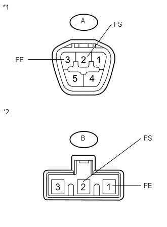
Measure the resistance according to the value(s) in the table below.
Standard Resistance
Tester Connection
Condition
Specified Condition
A-2 (FS) - B-2 (FS)
Always
Below 1 Ω
A-3 (FE) - B-1 (FE)
Always
Below 1 Ω
Table 2. Text in Illustration *1
Upper side
*2
Lower side (to fuel sender gauge assembly)
Table 3. Result Result
Proceed to
OK
A
NG (for 1ZR-FAE)
B
NG (for 2ZR-FAE)
C
NG (for 1WW)
D
-
INSPECT FUEL SENDER GAUGE ASSEMBLY
for 1ZR-FAE:
Remove the fuel sender gauge assembly (Click here).
Inspect the fuel sender gauge assembly (Click here).
for 2ZR-FAE:
Remove the fuel sender gauge assembly (Click here).
Inspect the fuel sender gauge assembly (Click here).
for 1WW:
Remove the fuel sender gauge assembly (Click here).
Inspect the fuel sender gauge assembly (Click here).
Table 4. Result Result
Proceed to
OK
A
NG (for 1ZR-FAE)
B
NG (for 2ZR-FAE)
C
NG (for 1WW)
D