RADIATOR INSTALLATION
PROCEDURE
-
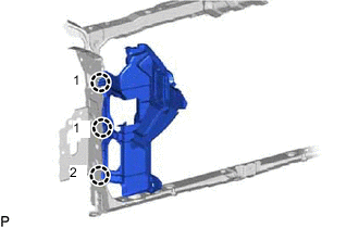
INSTALL LOWER RADIATOR SUPPORT
-
Install the 2 lower radiator supports.
-
-
INSTALL RADIATOR ASSEMBLY
-
Install the radiator assembly to the fan shroud with fan with the 2 bolts.
- Torque:
- 10.5 N*m { 107 kgf*cm, 8 ft.*lbf }
Note
Do not damage the core of the radiator assembly.
-
-
INSTALL RADIATOR ASSEMBLY WITH FAN
-
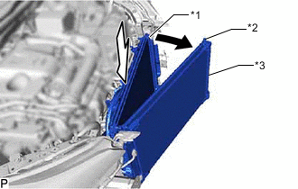
*1 Radiator Assembly with Fan *2 Intercooler Cooling Radiator Assembly *3 Condenser Assembly Move the LH side of the intercooler cooling radiator assembly and condenser assembly toward the front of the vehicle and install the radiator assembly with fan.
Note
-
Do not apply any excessive force to the intercooler cooling radiator assembly, condenser assembly and cooler pipe.
-
Do not move the intercooler cooling radiator assembly and condenser assembly LH toward the front of the vehicle more than necessary.
-
-
-
CONNECT INTERCOOLER RESERVOIR ASSEMBLY
-
Install the intercooler reservoir assembly to the fan shroud with the 2 bolts.
- Torque:
- 5.0 N*m { 51 kgf*cm, 44 in.*lbf }
-
-
CONNECT WIRE HARNESS
-
Connect the 2 connectors and attach the 7 clamps to connect the wire harness.
-
-
CONNECT NO. 2 INTERCOOLER COOLING WATER HOSE ASSEMBLY
-
Connect the No. 2 intercooler cooling water hose assembly to the intercooler cooling radiator assembly, and slide the clip to secure the hose.
-
Attach the 3 clamps.
-
-
CONNECT NO. 2 RADIATOR HOSE
-
Connect the No. 2 radiator hose to the radiator assembly, and slide the clip to secure the hose.
-
-
CONNECT NO. 1 RADIATOR HOSE
-
Connect the No. 1 radiator hose to the radiator assembly, and slide the clip to secure the hose.
-
Attach the clamp.
-
-
CONNECT NO. 2 WATER BY-PASS HOSE
-
Connect the No. 2 water by-pass hose to the radiator assembly, and slide the clip to secure the hose.
-
-
INSTALL FRONT SUSPENSION CROSSMEMBER SUB-ASSEMBLY
-
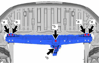
*a Bolt A *b Bolt B Install the front suspension crossmember sub-assembly with the 6 bolts.
- Torque:
- for bolt A
- 99 N*m { 1010 kgf*cm, 73 ft.*lbf }
- for bolt B
- 95 N*m { 969 kgf*cm, 70 ft.*lbf }
-
-
INSTALL FRONT SUSPENSION MEMBER REINFORCEMENT LH
-
INSTALL FRONT SUSPENSION MEMBER REINFORCEMENT RH
-
INSTALL NO. 2 FAN SHROUD
-
Attach the 2 claws to install the No. 2 fan shroud.
-
Install the 2 bolts.
- Torque:
- 10.5 N*m { 107 kgf*cm, 8 ft.*lbf }
-
-
INSTALL WATER BY-PASS PIPE
-
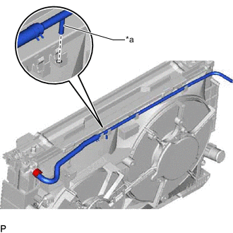
*a Protrusion Insert the protrusion of the water by-pass pipe into the hole of the No. 2 fan shroud.
-
Attach the 3 clamps to install the water by-pass pipe.
-
Connect the No. 3 water by-pass hose to the radiator assembly, and slide the clip to secure the hose.
-
-
CONNECT WATER BY-PASS HOSE
-
Connect the water by-pass hose to the radiator reservoir assembly, and slide the clip to secure the hose.
-
-
INSTALL UPPER RADIATOR SUPPORT SUB-ASSEMBLY
-

*a Bolt A *b Bolt B Install the upper radiator support sub-assembly with the 5 bolts.
- Torque:
- for bolt A
- 31 N*m { 316 kgf*cm, 23 ft.*lbf }
- for bolt B
- 12.5 N*m { 127 kgf*cm, 9 ft.*lbf }
-
w/ Dynamic Radar Cruise Control System:
Attach the 3 clamps.
-
w/o Dynamic Radar Cruise Control System:
Attach the 2 clamps.
-
Connect the 2 connectors.
-
-
CONNECT HOOD LOCK ASSEMBLY
-
Apply MP grease to the sliding parts of the hood lock assembly.
-
Attach the clamp and connect the hood lock assembly to the upper radiator support sub-assembly with the 3 bolts.
- Torque:
- 8.0 N*m { 82 kgf*cm, 71 in.*lbf }
-
Attach the 5 clamps and connect the connector.
-
-
INSTALL UPPER RADIATOR SUPPORT
-
Install the 2 upper radiator supports and 2 radiator support cushions with the 2 bolts.
- Torque:
- 19 N*m { 194 kgf*cm, 14 ft.*lbf }
-
-
INSTALL FRONT RADIATOR SIDE AIR GUIDE PLATE LH
-
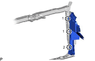
Attach the 3 claws in the order shown in the illustration to install the front radiator side air guide plate LH.
-
-
CONNECT FRONT RADIATOR SIDE AIR GUIDE PLATE RH
-
Attach the 3 claws in the order shown in the illustration to install the front radiator side air guide plate RH.
-
Attach the clamp to connect the thermistor assembly to the front radiator side air guide plate RH.
-
-
INSTALL MILLIMETER WAVE RADAR SENSOR ASSEMBLY (w/ Dynamic Radar Cruise Control System)
-
INSTALL BATTERY TRAY
-
INSTALL BATTERY
-
INSTALL BATTERY INSULATOR
-
INSTALL BATTERY CLAMP SUB-ASSEMBLY
-
INSTALL REAR ENGINE UNDER COVER LH
-
INSTALL REAR ENGINE UNDER COVER RH
-
INSTALL NO. 1 ENGINE UNDER COVER ASSEMBLY
-
INSTALL FRONT BUMPER REINFORCEMENT SUB-ASSEMBLY
-
for Sport Package:
-
except Sport Package:
-
-
CONNECT CABLE TO POSITIVE BATTERY TERMINAL
-
CONNECT CABLE TO NEGATIVE BATTERY TERMINAL
Note
When disconnecting the cable, some systems need to be initialized after the cable is reconnected.
-
ADD ENGINE COOLANT
-
ADD COOLANT (for Intercooler)
-
INSPECT FOR COOLANT LEAK
-
INSPECT FOR COOLANT LEAK (for Intercooler)
-
ADJUST MILLIMETER WAVE RADAR SENSOR ASSEMBLY (w/ Dynamic Radar Cruise Control System)