CAMSHAFT OIL CONTROL VALVE(for Exhaust Side) REMOVAL
PROCEDURE
REMOVE FRONT WHEEL RH
REMOVE REAR ENGINE UNDER COVER RH
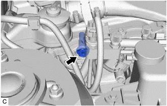
REMOVE CAMSHAFT TIMING OIL CONTROL SOLENOID ASSEMBLY (for Exhaust Side)
SET NO. 1 CYLINDER TO TDC/COMPRESSION
-
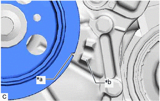
*a
Timing Mark (Cutout)
*b
Protrusion
Turn the crankshaft pulley clockwise until its timing mark (cutout) is aligned with the protrusion on the timing chain cover assembly as shown in the illustration.
-
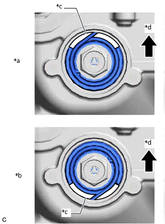
*a
Correct
*b
Incorrect
*c
Cutout
*d
Up
Check that the cutout of the camshaft timing gear assembly is at the top.
Tip:If the cutout of the camshaft timing gear assembly is not at the top, turn the crankshaft 360° clockwise and align the timing mark (cutout) of the crankshaft pulley with the protrusion on the timing chain cover assembly again.
-
REMOVE CAMSHAFT TIMING GEAR BOLT
-
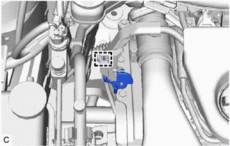
Disengage the clamp to remove the wire harness clamp bracket from the engine wire.
-
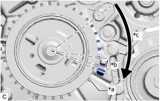
*a
Tooth
*b
10°
*c
60 +/- 20°
Turn the crankshaft pulley clockwise approximately 60° (+/- 20°).
Tip:The crankshaft pulley can be turned approximately 60° by turning it until 6 teeth of the sensor rotor have passed.
-
While holding the crankshaft pulley, remove the camshaft timing gear bolt.
Note:If the camshaft timing gear bolt has been struck or dropped, replace it.
Do not turn the crankshaft pulley after removing the camshaft timing gear bolt.
-