VEHICLE PROXIMITY NOTIFICATION SYSTEM TERMINALS OF ECU
CHECK VEHICLE APPROACHING SPEAKER CONTROLLER
-
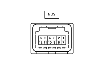
Disconnect the N39 vehicle approaching speaker controller connector.
Measure the voltage and resistance according to the value(s) in the table below.
Terminal No. (Symbol)
Wiring Color
Terminal Description
Condition
Specified Condition
N39-1 (IG) - Body ground
L - Body ground
IG power supply
Power switch on (IG)
11 to 14 V
Power switch off
Below 1 V
N39-7 (GND) - Body ground
W-B - Body ground
Ground
Always
Below 1 Ω
Reconnect the N39 vehicle approaching speaker controller connector.
Measure the voltage and check for pulses according to the value(s) in the table below.
Terminal No. (Symbol)
Wiring Color
Terminal Description
Condition
Specified Condition
N39-2 (STP) - N39-7 (GND)
Y - W-B
Stop light signal input
Power switch off, brake pedal depressed
8 V or higher
Power switch off, brake pedal released
Below 1 V
N39-3 (SP+) - N39-8 (SP-)
P - R
Vehicle approaching speaker output
Vehicle approaching speaker operating
A waveform synchronized with the sound is output.
N39-5 (SW) - N39-7 (GND)*
SB - W-B
Vehicle approaching speaker switch signal
Power switch on (IG), vehicle approaching speaker switch on
6 V or higher
Power switch on (IG), vehicle approaching speaker switch off
Below 1 V
N39-6 (SPD) - N39-7 (GND)
V - W-B
Speed signal input
Driving at approximately 20 km/h (12 mph)
Pulse generation
(See Waveform 1)
N39-9 (PRST) - N39-7 (GND)
LG - W-B
SIL communication signal
Power switch on (IG), during transmission
Pulse generation
(See Waveform 2)
N39-10 (IND) - N39-7 (GND)*
W - W-B
No. 2 combination switch assembly (vehicle approaching speaker switch) indicator signal
Power switch on (IG), vehicle approaching speaker switch on
Below 2.8 V
Power switch on (IG), vehicle approaching speaker switch off
11 to 14 V
N39-11 (KOK) - N39-7 (GND)
G - W-B
Permission signal
Power switch on (READY), shift lever in P
Below 2.3 V
Power switch on (READY), engine stopped and shift lever not in P
8 V or higher
*: w/ Vehicle Approaching Speaker Switch
-
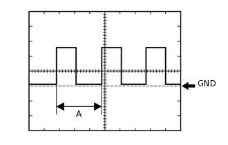
Waveform 1
Item
Condition
Tester Connection
N39-6 (SPD) - N39-7 (GND)
Tool setting
5 V/DIV., 20 ms./DIV.
Vehicle condition
Driving at approximately 20 km/h (12 mph)
Tip:When the system is functioning normally, one wheel revolution generates 4 pulses. As the vehicle speed increases, the width indicated by (A) in the illustration narrows.
-
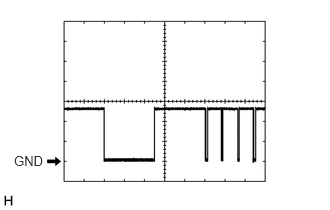
Waveform 2
Item
Condition
Tester Connection
N39-9 (PRST) - N39-7 (GND)
Tool setting
5 V/DIV., 10 ms./DIV.
Vehicle condition
Power switch on (IG), during transmission
-
CHECK HYBRID VEHICLE CONTROL ECU
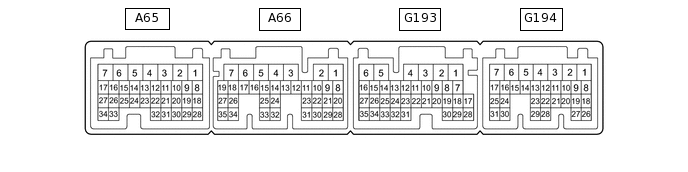
Disconnect the A65, A66 and G193 hybrid vehicle control ECU connectors.
Measure the voltage and resistance according to the value(s) in the table below.
Terminal No. (Symbol)
Wiring Color
Terminal Description
Condition
Specified Condition
A65-1 (+B2) - G193-6 (E1)
W - BR
IG power supply
Power switch on (IG)
11 to 14 V
Power switch off
Below 1 V
A65-3 (IG2) - G193-6 (E1)
B - BR
IG power supply
Power switch on (IG)
11 to 14 V
Power switch off
Below 1 V
A66-4 (+B1) - G193-6 (E1)
SB - BR
IG power supply
Power switch on (IG)
11 to 14 V
Power switch off
Below 1 V
G193-6 (E1) - Body ground
BR - Body ground
Ground
Always
Below 1 Ω
Reconnect the A60, A61 and G193 hybrid vehicle control ECU connectors.
Measure the voltage according to the value(s) in the table below.
Terminal No. (Symbol)
Wiring Color
Terminal Description
Condition
Specified Condition
A65-15 (STP) - G193-6 (E1)
L - BR
Stop light switch
Brake pedal depressed
11 to 14 V
Brake pedal released
0 to 1.5 V
G193-7 (KOK) - G193-6 (E1)
G - BR
Permission signal
Power switch on (READY), shift lever in P
Below 2.3 V
Power switch on (READY), engine stopped and shift lever not in P
8 V or higher