AIR CONDITIONING SYSTEM (for Automatic Air Conditioning System) Blower Motor Circuit
DESCRIPTION
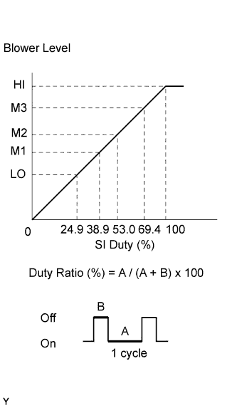
The blower with fan motor sub-assembly is operated by signals from the air conditioning amplifier. Blower with fan motor sub-assembly speed signals are determined by changes in the duty ratio*.
The blower motor control controls the blower with fan motor sub-assembly speed. The blower motor control reads the signal from the air conditioning amplifier assembly and controls rotation and speed.
Tech Tips
*: The duty ratio is the ratio of the blower with fan motor sub-assembly on time (A) to the total of the blower with fan motor sub-assembly on and off time (A + B).
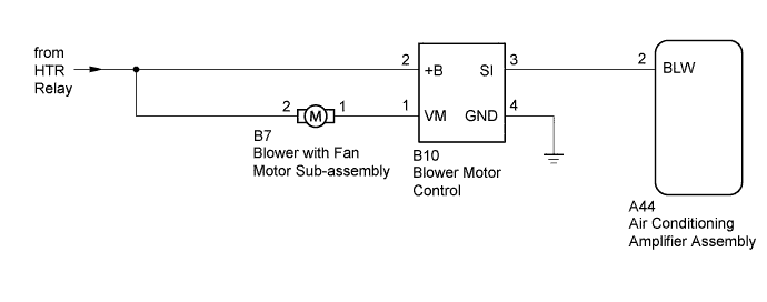
WIRING DIAGRAM
INSPECTION PROCEDURE
Note
Inspect the relays for circuits related to this system before performing the following inspection procedure.
PROCEDURE
-
PERFORM ACTUATOR CHECK
-
Enter actuator check mode Click here.
-
Place your hand in front of a vent and check that the air flow level changes according to the display code.
Display Code Blower Level 0 0 1 1 2 16 3 16 4 16 5 16 6 16 7 16 8 16 9 31 OK Blower level changes in accordance with each display code. Tech Tips
The progression through the steps of the actuator check can be changed from automatic to manual by pressing the front DEF switch.
NG 
CHECK HARNESS AND CONNECTOR (BLOWER MOTOR CONTROL - AIR CONDITIONING AMPLIFIER AND BODY GROUND) Click here
OK 
PROCEED TO NEXT SUSPECTED AREA SHOWN IN PROBLEM SYMPTOMS TABLE Click here
-
-
CHECK HARNESS AND CONNECTOR (BLOWER MOTOR CONTROL - AIR CONDITIONING AMPLIFIER AND BODY GROUND)
-
Disconnect the B10 blower motor control connector.
-
Disconnect the A44 air conditioning amplifier assembly connector.
-
Measure the resistance according to the value(s) in the table below.
Standard Resistance Tester Connection Condition Specified Condition B10-3 (SI) - A44-2 (BLW) Always Below 1 Ω B10-4 (GND) - Body ground B10-3 (SI) - Body ground Always 10 kΩ or higher B10-2 (+B) - Body ground B10-1 (VM) - Body ground
NG 
REPAIR OR REPLACE HARNESS OR CONNECTOR
OK 
-
-
INSPECT BLOWER WITH FAN MOTOR SUB-ASSEMBLY
-
Remove the blower with fan motor sub-assembly Click here.
-
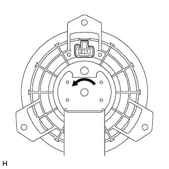
Apply battery voltage to the blower with fan motor sub-assembly and check the operation of the blower motor.
OK Measurement Condition Specified Condition Battery positive (+) → Terminal 2
Battery negative (-) → Terminal 1
The blower motor operates smoothly
NG
REPLACE BLOWER WITH FAN MOTOR SUB-ASSEMBLY Click here
OK
-
-
CHECK HARNESS AND CONNECTOR (BLOWER MOTOR CONTROL AND BLOWER WITH FAN MOTOR - BATTERY)
-
Disconnect the B10 blower motor control connector.
-
Disconnect the B7 blower with fan motor sub-assembly connector.
-
Measure the voltage and resistance according to the value(s) in the table below.
Standard Voltage Tester Connection Switch Condition Specified Condition B10-2 (+B) - Body ground
-
Ignition switch ON
-
Blower switch on (LO level)
11 to 14 V
-
Ignition switch ON
-
Blower switch off
Below 1 V B7-2 - Body ground
-
Ignition switch ON
-
Blower switch on (LO level)
11 to 14 V
-
Ignition switch ON
-
Blower switch off
Below 1 V Standard Resistance Tester Connection Condition Specified Condition B7-1 - Body ground Always 10 kΩ or higher B7-2 - Body ground -
NG
REPAIR OR REPLACE HARNESS OR CONNECTOR
OK
-
-
CHECK HARNESS AND CONNECTOR (BLOWER MOTOR CONTROL - BLOWER WITH FAN MOTOR)
-
Disconnect the B10 blower motor control connector.
-
Disconnect the B7 blower with fan motor sub-assembly connector.
-
Measure the resistance according to the value(s) in the table below.
Standard Resistance Tester Connection Condition Specified Condition B10-1 (VM) - B7-1 Always Below 1 Ω
NG
REPAIR OR REPLACE HARNESS OR CONNECTOR
OK
-
-
CHECK AIR CONDITIONING AMPLIFIER ASSEMBLY
-
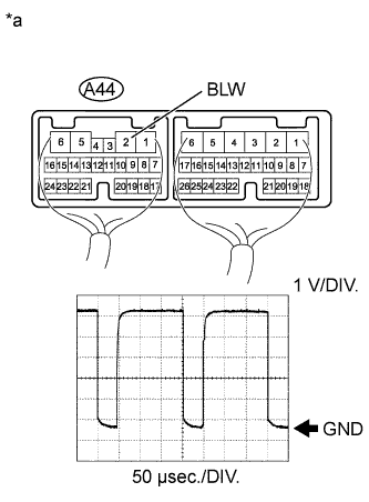
Text in Illustration *a Component with harness connected
(Air Conditioning Amplifier Assembly)
Remove the air conditioning amplifier assembly with its connectors still connected Click here.
-
Using an oscilloscope, check the waveform of the amplifier.
Measurement Condition Item Content Tester Connection A44-2 (BLW) - Body ground Tool Setting 1 V/DIV., 50 μsec./DIV. Condition Ignition switch ON, Blower switch on (LO level) OK Waveform is as shown in the illustration. Tech Tips
Waveform varies depending on the blower switch setting.
NG
REPLACE AIR CONDITIONING AMPLIFIER ASSEMBLY Click here
OK
REPLACE BLOWER MOTOR CONTROL Click here
-