SEAT BELT WARNING SYSTEM Driver Side Seat Belt Warning Light does not Operate
| DTC Code | DTC Name |
|---|---|
| Driver Side Seat Belt Warning Light does not Operate |
DESCRIPTION
The combination meter assembly blinks or turns off the front seat belt warning light on the combination meter assembly in accordance with the state of the front seat inner belt assembly (driver seat).
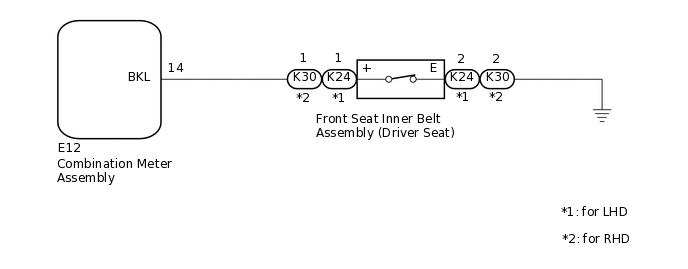
WIRING DIAGRAM
PROCEDURE
READ VALUE USING GTS
Connect the GTS to the DLC3.
Turn the ignition switch to ON.
Turn the GTS on.
Enter the following menus: Body Electrical / Combination Meter / Data List.
Read the Data List according to the display on the GTS.
Body Electrical > Combination Meter > Data List
Tester Display
Measurement Item
Range
Normal Condition
Diagnostic Note
Driver Side Seatbelt Buckle Switch
Driver seat belt buckle switch signal
ON or OFF
OFF: Driver seat belt fastened
ON: Driver seat belt unfastened
-
Body Electrical > Combination Meter > Data List
Tester Display
Driver Side Seatbelt Buckle Switch
OK
The GTS display changes correctly in response to the driver seat belt condition.
Result
Proceed to
OK
NG
INSPECT FRONT SEAT INNER BELT ASSEMBLY (DRIVER SEAT)
Remove the front seat inner belt assembly (driver seat).
Inspect the front seat inner belt assembly (driver seat).
Result
Proceed to
OK
NG
CHECK HARNESS AND CONNECTOR (COMBINATION METER ASSEMBLY - FRONT SEAT INNER BELT ASSEMBLY (DRIVER SEAT) - BODY GROUND)
Disconnect the E12 combination meter assembly connector.
Measure the resistance according to the value(s) in the table below.
Standard Resistance
Table 1. for LHD Tester Connection
Condition
Specified Condition
E12-14 (BKL) - K24-1 (+)
Always
Below 1 Ω
E12-14 (BKL) or K24-1 (+) - Body ground
Always
10 kΩ or higher
K24-2 (E) - Body ground
Always
Below 1 Ω
Table 2. for RHD Tester Connection
Condition
Specified Condition
E12-14 (BKL) - K30-1 (+)
Always
Below 1 Ω
E12-14 (BKL) or K30-1 (+) - Body ground
Always
10 kΩ or higher
K30-2 (E) - Body ground
Always
Below 1 Ω
Result
Proceed to
OK
NG
NG REPAIR OR REPLACE HARNESS OR CONNECTOR