SFI SYSTEM(w/ Canister Pump Module), Diagnostic DTC:P010F64
| DTC Code | DTC Name |
|---|---|
| P010F64 | Mass or Volume Air Flow Sensor A/B Correlation Signal Plausibility Failure |
DESCRIPTION
Refer to DTC P010012.
| DTC No. | Detection Item | DTC Detection Condition | Trouble Area | MIL | Memory | Note |
|---|---|---|---|---|---|---|
| P010F64 | Mass or Volume Air Flow Sensor A/B Correlation Signal Plausibility Failure | All of the following conditions are met (2 trip detection logic).
|
|
Comes on | DTC stored | SAE: P010F |
MONITOR DESCRIPTION
The mass air flow meter sub-assembly is a sensor that measures the amount of air flowing through the throttle valve. The ECM uses this information to determine fuel injection timing and to provide an appropriate air fuel ratio. Inside the mass air flow meter sub-assembly, there is a heated platinum wire which is exposed to the flow of intake air. By applying a specific electrical current to the wire, the ECM heats it to a specific temperature. The flow of incoming air cools both the wire and an internal thermistor, affecting their resistance. To maintain a constant current value, the ECM varies the voltage applied to the mass air flow meter sub-assembly. The voltage level is proportional to the airflow through the sensor, and the ECM uses it to calculate the intake air volume.
The ECM monitors the average engine load value ratio to check the mass air flow meter sub-assembly for malfunctions. The average engine load value ratio is obtained by comparing the average engine load calculated from the mass air flow meter sub-assembly output to the average engine load estimated from the driving conditions, such as the engine speed and the throttle opening angle. If the average engine load value ratio is below the threshold value, the ECM determines that the intake air volume is low, and if the average engine load value ratio is above the threshold value, the ECM determines that the intake air volume is high. If either or these conditions is detected in 2 consecutive driving cycles, the ECM illuminates the MIL and stores this DTC.
MONITOR STRATEGY
| Required Sensors/Components (Main) | Mass air flow meter sub-assembly |
| Required Sensors/Components (Related) | Crankshaft position sensor Camshaft position sensor Engine coolant temperature sensor Throttle position sensor |
| Frequency of Operation | Continuous |
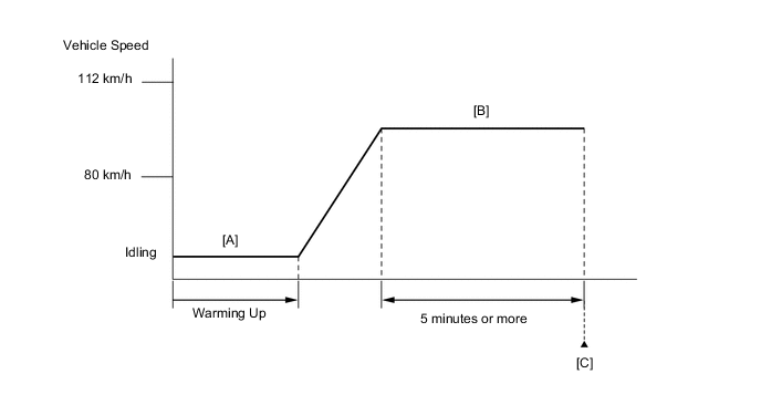
CONFIRMATION DRIVING PATTERN
-
Connect the GTS to the DLC3.
-
Turn the engine switch on (IG).
-
Turn the GTS on.
-
Clear the DTCs (even if no DTCs are stored, perform the clear DTC procedure).
-
Turn the engine switch off and wait for at least 30 seconds.
-
Turn the engine switch on (IG).
-
Turn the GTS on.
-
Start the engine and warm it up until the engine coolant temperature is 70°C (158°F) or higher [A].
-
Drive the vehicle at approximately 80 km/h (50 mph) to 112 km/h (70 mph) for 5 minutes or more [B].
CAUTION:
When performing the confirmation driving pattern, obey all speed limits and traffic laws.
Tech Tips
Drive while keeping the engine load as stable as possible.
-
Enter the following menus: Powertrain / Engine / Trouble Codes [C].
-
Read the pending DTCs.
Tech Tips
-
If a pending DTC is output, the system is malfunctioning.
-
If a pending DTC is not output, perform the following procedure.
-
-
Enter the following menus: Powertrain / Engine / Utility / All Readiness.
-
Input the DTC: P010F64.
-
Check the DTC judgment result.
GTS Display Description NORMAL
-
DTC judgment completed
-
System normal
ABNORMAL
-
DTC judgment completed
-
System abnormal
INCOMPLETE
-
DTC judgment not completed
-
Perform driving pattern after confirming DTC enabling conditions
Tech Tips
-
If the judgment result is NORMAL, the system is normal.
-
If the judgment result is ABNORMAL, the system is malfunctioning.
-
If the judgment result is INCOMPLETE, perform steps [B] through [C] again.
-
CAUTION / NOTICE / HINT
Tech Tips
Read Freeze Frame Data using the GTS. The ECM records vehicle and driving condition information as Freeze Frame Data the moment a DTC is stored. When troubleshooting, Freeze Frame Data can help determine if the vehicle was moving or stationary, if the engine was warmed up or not, if the air fuel ratio was lean or rich, and other data from the time the malfunction occurred.
PROCEDURE
-
CHECK ANY OTHER DTCS OUTPUT (IN ADDITION TO DTC P010F64)
-
Connect the GTS to the DLC3.
-
Turn the engine switch on (IG).
-
Turn the GTS on.
-
Enter the following menus: Powertrain / Engine / Trouble Codes.
-
Read the DTCs.
Powertrain > Engine > Trouble CodesResult Result Proceed to DTC P010F64 is output A DTC P010F64 and other DTCs are output B Tech Tips
If any DTCs other than P010F64 are output, troubleshoot those DTCs first.
B 
GO TO DTC CHART Click here
A 
-
-
CHECK INTAKE SYSTEM
-
Check the intake system for vacuum leaks.
OK No leaks from intake system. Tech Tips
Perform "Inspection After Repair" after repairing or replacing the intake system.
Result Proceed to OK NG
NG
REPAIR OR REPLACE INTAKE SYSTEM
OK
-
-
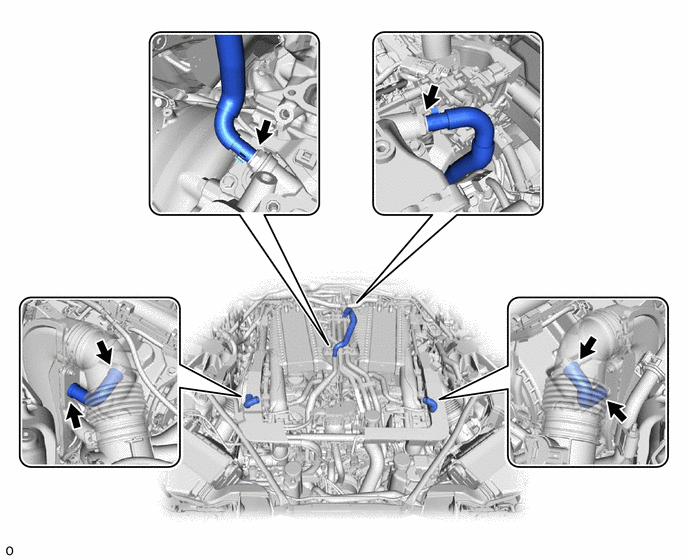
CHECK PCV VALVE AND HOSE CONNECTIONS
-
Check the PCV hose connections.
-
Check the PCV valve.
OK PCV hose and PCV valve are connected correctly and are not damaged. Result Proceed to OK NG
NG
REPAIR OR REPLACE PCV VALVE OR HOSE
OK
-
-
REPLACE MASS AIR FLOW METER SUB-ASSEMBLY (BANK 1 AND BANK 2)
-
Replace the mass air flow meter sub-assembly (bank 1 and bank 2).
Tech Tips
Perform "Inspection After Repair" after replacing the mass air flow meter sub-assembly.
Result Proceed to NEXT
NEXT
-
-
CLEAR DTC
-
Connect the GTS to the DLC3.
-
Turn the engine switch on (IG).
-
Turn the GTS on.
-
Clear the DTCs.
Powertrain > Engine > Clear DTCs -
Turn the engine switch off and wait for at least 30 seconds.
Result Proceed to NEXT
NEXT
-
-
CONFIRM WHETHER MALFUNCTION HAS BEEN SUCCESSFULLY REPAIRED
-
Drive the vehicle in accordance with the driving pattern described in Confirmation Driving Pattern.
-
Enter the following menus: Powertrain / Engine / Utility / All Readiness.
Powertrain > Engine > UtilityTester Display All Readiness -
Input the DTC: P010F64.
-
Check the DTC judgment result.
Result GTS Display Description NORMAL
-
DTC judgment completed
-
System normal
ABNORMAL
-
DTC judgment completed
-
System abnormal
INCOMPLETE
-
DTC judgment not completed
-
Perform driving pattern after confirming DTC enabling conditions
Result Proceed to NEXT -
NEXT
END
-