ECD SYSTEM (w/o EGR Cooler), Diagnostic DTC:P0200
| DTC Code | DTC Name |
|---|---|
| P0200 | Injector Circuit / Open |
DESCRIPTION
Tech Tips
-
For more information on the injector driver (EDU) Click here.
-
If DTC P0200 is present, refer to the "Diagnostic Trouble Code (DTC) Table for Common Rail System" Click here.
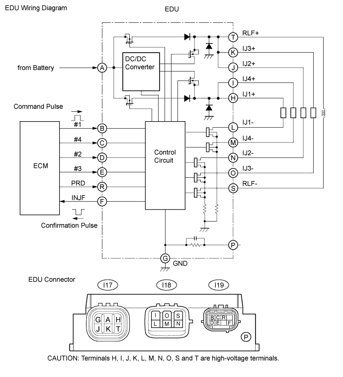
The EDU drives the injectors at high speed. The EDU has realized high-speed driving under high-pressure fuel conditions using the DC/DC converter, which provides a high voltage and the quick-charging system. Soon after the EDU receives an injection command (IJT) signal from the ECM, the EDU responds to the command with an injector injection confirmation (IJF) signal when the current is applied to the injector.
| DTC No. | DTC Detection Condition | Trouble Area |
|---|---|---|
| P0200 |
After engine is started, there is no IJF signal from EDU to ECM, despite ECM sending IJT signals to EDU (1 trip detection logic) |
|
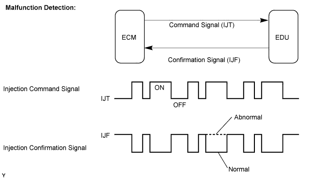
MONITOR DESCRIPTION
P0200 (Open or short in injector driver (EDU) or injector circuit):The ECM continuously monitors both injection command (IJT) signals and injection confirmation (IJF) signal. This DTC will be set if the ECM judges that the number of IJT signals and IJF signals are inconsistent.
The injectors are grounded over a Field Effect Transistor (FET) and a serial resistor. This resistor creates a voltage drop, which is monitored by the EDU, in relation to the current drawn by the injector. When the injector current becomes too high, the voltage drop over the resistor becomes higher than a specified level and for that injector no IJF signal is sent to the ECM.
P0200 refers to a malfunction of injector drive circuit or injector circuit.
If this DTC is set, the ECM enters the fail-safe mode and limits engine power. The fail-safe mode continues until the ignition switch is turned OFF.
Tech Tips
The problem area can be identified by checking the waveform at the following terminals.
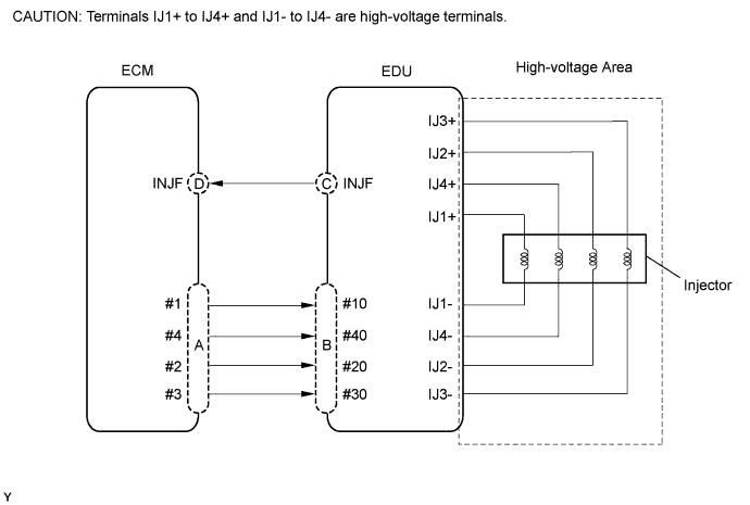
Tech Tips
A and D are on the ECM side, and B and C are on the EDU side.
| Malfunction Point | Trouble Area |
|---|---|
| A |
|
| B (If A is normal) |
|
| C (If A and B are normal) |
|
| D (If A, B and C are normal) |
|
-
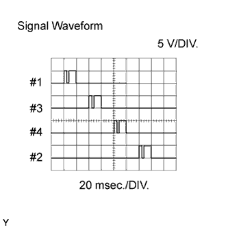
Reference: Inspection using the oscilloscope.
During idling, the correct waveform is as shown in the diagram.
Inspection Point Specified Condition A and B Correct waveform is as shown -
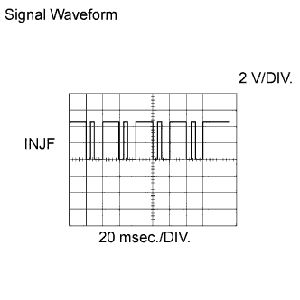
Reference: Inspection using the oscilloscope.
During idling, the correct waveform is as shown in the diagram.
Inspection Point Specified Condition C and D Correct waveform is as shown
MONITOR STRATEGY
| Required sensor | INJF signal from EDU |
| Frequency of operation | Continuous |
| Duration | 10 seconds |
| MIL operation | 1 driving cycle |
TYPICAL ENABLING CONDITIONS
| Item | Specification | |
|---|---|---|
| Minimum | Maximum | |
| Engine speed | 500 rpm | - |
| Battery voltage | 11 V | - |
| Ignition switch | ON | ON |
TYPICAL MALFUNCTION THRESHOLDS
| Threshold |
|---|
| Injection missing counter* for all cylinders, or for one individual cylinder, reaches specified number (taking approximately 1 second from starting engine) *: Increases when no IJF signal is received from the EDU despite the ECM sending the IJT signals. |
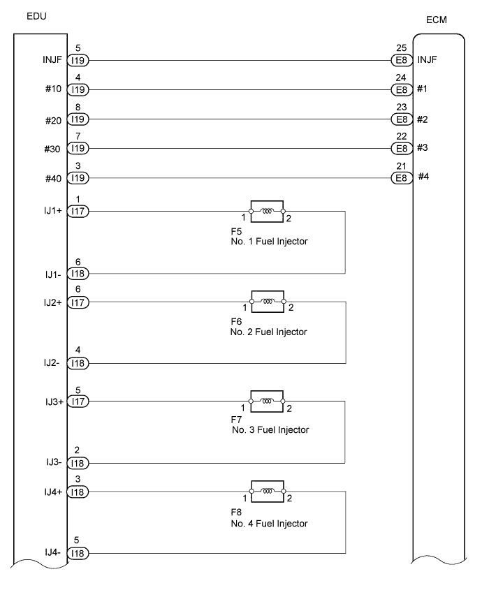
WIRING DIAGRAM
INSPECTION PROCEDURE
Note
After replacing the ECM, the new ECM needs registration Click here and initialization Click here.
Tech Tips
-
If P0200 and P1271 are present simultaneously, there is an open in the INJF wire harness between the EDU and ECM, or there is an open in the wire harness for both the injectors and pressure discharge valve.
-
Read freeze frame data using the intelligent tester. Freeze frame data records the engine condition when malfunctions are detected. When troubleshooting, freeze frame data can help determine if the vehicle was moving or stationary, if the engine was warmed up or not, and other data from the time the malfunction occurred.
PROCEDURE
-
INSPECT INJECTOR ASSEMBLY
-
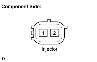
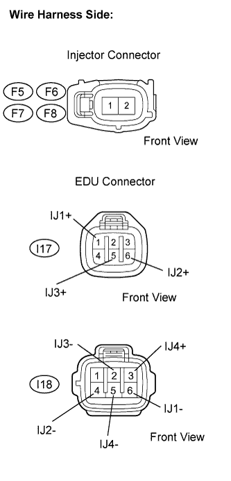
Disconnect the F5, F6, F7 and F8 injector connectors.
-
Measure the resistance of the injection assembly.
Standard resistance Tester Connection Condition Specified Condition 1 - 2 20°C (68°F) 0.42 to 0.52 Ω
NG 
REPLACE INJECTOR ASSEMBLY Click here
OK 
-
-
CHECK HARNESS AND CONNECTOR (INJECTOR DRIVER [EDU] - INJECTOR ASSEMBLY)
-
Check the harness and connector between the injector and EDU (INJ terminal).
-
Disconnect the F5, F6, F7 and F8 injector connectors.
-
Disconnect the I17 and/or I18 EDU connectors.
-
Measure the resistance of the wire harness side connector.
Standard resistance (Check for open) Tester Connection Specified Condition F5-1 - IJ1+ (I17-1) Below 1 Ω F6-1 - IJ2+ (I17-6) F7-1 - IJ3+ (I17-5) F8-1 - IJ4+ (I18-3) F5-2 - IJ1- (I18-6) F6-2 - IJ2- (I18-4) F7-2 - IJ3- (I18-2) F8-2 - IJ4- (I18-5) Standard resistance (Check for short) Tester Connection Specified Condition F5-1 or IJ1+ (I17-1) - Body ground 10 kΩ or higher F6-1 or IJ2+ (I17-6) - Body ground F7-1 or IJ3+ (I17-5) - Body ground F8-1 or IJ4+ (I18-3) - Body ground F5-2 or IJ1- (I18-6) - Body ground F6-2 or IJ2- (I18-4) - Body ground F7-2 or IJ3- (I18-2) - Body ground F8-2 or IJ4- (I18-5) - Body ground
-
NG
REPAIR OR REPLACE HARNESS OR CONNECTOR
OK
-
-
CHECK HARNESS AND CONNECTOR (INJECTOR DRIVER [EDU] - ECM)
-
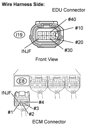
Disconnect the I19 EDU connector.
-
Disconnect the E8 ECM connector.
-
Measure the resistance of the wire harness side connector.
Standard resistance (Check for open) Tester Connection Specified Condition #10 (I19-4) - #1 (E8-24) Below 1 Ω #20 (I19-8) - #2 (E8-23) #30 (I19-7) - #3 (E8-22) #40 (I19-3) - #4 (E8-21) INJF (I19-5) - INJF (E8-25) Standard resistance (Check for short) Tester Connection Specified Condition #10 (I19-4) or #1 (E8-24) - Body ground 10 kΩ or higher #20 (I19-8) or #2 (E8-23) - Body ground #30 (I19-7) or #3 (E8-22) - Body ground #40 (I19-3) or #4 (E8-21) - Body ground INJF (I19-5) or INJF (E8-25) - Body ground
NG
REPAIR OR REPLACE HARNESS OR CONNECTOR
OK
-
-
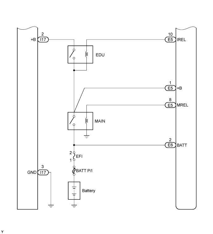
INSPECT INJECTOR DRIVER (EDU) (BATTERY VOLTAGE)
-
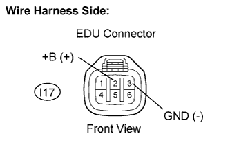
Disconnect the I17 EDU connector.
-
Turn the ignition switch ON.
-
Measure the voltage of the EDU connector.
Standard voltage Tester Connection Specified Condition +B (I17-2) - GND (I17-3) 11 to 14 V
NG
CHECK INJECTOR DRIVER POWER SOURCE CIRCUIT (BATTERY - EDU)
OK
-
-
REPLACE INJECTOR DRIVER (EDU)
-
Replace injector driver Click here.
NEXT
-
-
CHECK WHETHER DTC OUTPUT RECURS
-
Connect the intelligent tester to the DLC3.
-
Turn the ignition switch ON.
-
Turn the tester ON.
-
Clear DTCs Click here.
-
Start the engine.
-
Allow the engine to idle for 30 seconds or more.
-
Enter the following menus: Powertrain / Engine and ECT / DTC.
-
Read the DTCs.
Result Display (DTC Output) Proceed to No output A P0200 B Tech Tips
If the engine does not stat, replace the ECM.
B
REPLACE ECM Click here
A 
END
-