POWER MIRROR CONTROL SYSTEM Power Mirror Surface Position is not Memorized
| DTC Code | DTC Name |
|---|---|
| Power Mirror Surface Position is not Memorized |
SYSTEM DESCRIPTION
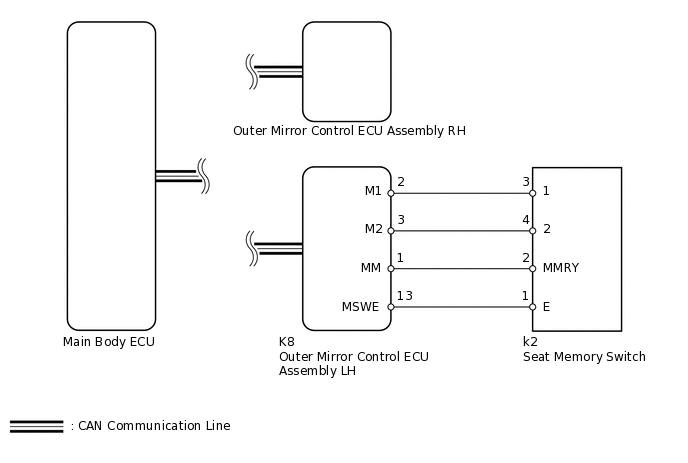
If the M1 or M2 seat memory switch is pressed, the outer mirror control ECU assembly LH detects the switch operation and sends the seat memory switch signal to the main body ECU (multiplex network body ECU) via CAN communication. Upon receiving the seat memory switch signal, the main body ECU (multiplex network body ECU) sends the memory request signal to each outer mirror control ECU assembly via CAN communication. When receiving this signal, each outer mirror control ECU assembly stores the mirror surface position based on information from the mirror position sensor, which is built into the outer rear view mirror assembly.
WIRING DIAGRAM
PROCEDURE
CHECK CAN COMMUNICATION SYSTEM
Check if a CAN communication DTC is output.
Result
Result
Proceed to
DTC is not output
A
DTC is output
B
READ VALUE USING INTELLIGENT TESTER (SEAT MEMORY SWITCH)
Using the intelligent tester, read the Data List.
Body Electrical > Mirror L > Data List
Tester Display
Measurement Item
Range
Normal Condition
Diagnostic Note
Seat Memory Switch1
Seat memory switch M1 signal
ON or OFF
ON: Seat memory switch M1 on
OFF: Seat memory switch M1 off
-
Seat Memory Switch2
Seat memory switch M2 signal
ON or OFF
ON: Seat memory switch M2 on
OFF: Seat memory switch M2 off
-
Seat Memory Set SW
Seat memory switch SET signal
ON or OFF
ON: Seat memory switch SET on
OFF: Seat memory switch SET off
-
OK
On intelligent tester screen, each item changes between ON and OFF according to above chart.
Result
Result
OK
NG
NG INSPECT SEAT MEMORY SWITCHClick here
CHECK SEAT MEMORY SWITCH FUNCTION (SEAT POSITION MEMORY FUNCTION)
Perform a seat memory operation properly.
When any seat memory switch (M1 or M2 switch) is pressed, check that the driver side seat moves to the memorized position.
OK
Driver side seat moves to memorized position.
Result
Result
OK
NG
READ VALUE USING INTELLIGENT TESTER (MIRROR POSITION MEMORY)
Using the intelligent tester, read the Data List.
Body Electrical > Mirror L > Data List
Tester Display
Measurement Item
Range
Normal Condition
Diagnostic Note
Mirror Memory No.1
Mirror position memorized in memory switch M1
OFF or ON
ON: Memorized
OFF: Not memorized
-
Mirror Memory No.2
Mirror position memorized in memory switch M2
OFF or ON
ON: Memorized
OFF: Not memorized
-
Body Electrical > Mirror R > Data List
Tester Display
Measurement Item
Range
Normal Condition
Diagnostic Note
Mirror Memory No.1
Mirror position memorized in memory switch M1
OFF or ON
ON: Memorized
OFF: Not memorized
-
Mirror Memory No.2
Mirror position memorized in memory switch M2
OFF or ON
ON: Memorized
OFF: Not memorized
-
OK
"ON" is displayed on intelligent tester.
Result
Result
Proceed to
OK
A
NG (for Driver Side)
B
NG (for Passenger Side)
C
INSPECT SEAT MEMORY SWITCH
-
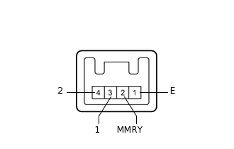
Remove the seat memory switch.
Measure the resistance according to the value(s) in the table below.
Standard Resistance
Tester Connection
Switch Condition
Specified Condition
3 (1) - 1 (E)
Seat memory switch M1 pressed
Below 1 Ω
4 (2) - 1 (E)
Seat memory switch M2 pressed
Below 1 Ω
2 (MMRY) - 1 (E) Seat memory
Seat memory switch SET pressed
Below 1 Ω
Result
Result
OK
NG
-
CHECK HARNESS AND CONNECTOR (OUTER MIRROR CONTROL ECU - SEAT MEMORY SWITCH)
Disconnect the K8 ECU connector.
Disconnect the k2 switch connector.
Measure the resistance according to the value(s) in the table below.
Standard Resistance
Tester Connection
Switch Condition
Specified Condition
K8-2 (M1) - k2-3 (1)
Always
Below 1 Ω
K8-3 (M2) - k2-4 (2)
Always
Below 1 Ω
K8-1 (MM) - k2-2 (MMRY)
Always
Below 1 Ω
K8-13 (MSWE) - k2-1 (E)
Always
Below 1 Ω
K8-2 (M1) - Body ground
Always
10 kΩ or higher
K8-3 (M2) - Body ground
Always
10 kΩ or higher
K8-1 (MM) - Body ground
Always
10 kΩ or higher
K8-13 (MSWE) - Body ground
Always
10 kΩ or higher
Result
Result
OK
NG
NG REPAIR OR REPLACE HARNESS OR CONNECTOR