SFI SYSTEM(w/o Canister Pump Module), Diagnostic DTC:P136201, P136301
| DTC Code | DTC Name |
|---|---|
| P136201 | "B" Camshaft Position Actuator Bank 1 General Electrical Failure |
| P136301 | "B" Camshaft Position Actuator Bank2 General Electrical Failure |
DESCRIPTION
Refer to DTC P001001.
| DTC No. | Detection Item | DTC Detection Condition | Trouble Area | MIL | Memory | Note |
|---|---|---|---|---|---|---|
| P136201 | "B" Camshaft Position Actuator Bank 1 General Electrical Failure | While engine is running, malfunction in rotation direction signal (VTD) of cam timing control motor with EDU assembly (bank 1) is detected for 3 seconds (1 trip detection logic). |
|
Comes on | DTC stored | SAE: P1362 |
| P136301 | "B" Camshaft Position Actuator Bank2 General Electrical Failure | While engine is running, malfunction in rotation direction signal (VTD) of cam timing control motor with EDU assembly (bank 2) is detected for 3 seconds (1 trip detection logic). |
|
Comes on | DTC stored | SAE: P1363 |
| Vehicle Condition | Fail-Safe |
|---|---|
|
The cam timing control motor with EDU assembly is operated to the most retarded position. |
MONITOR DESCRIPTION
This DTC is output when a rotation direction signal malfunction is detected in the cam timing control motor with EDU assembly. While the engine is running, if a rotation direction signal (VTD) malfunction is detected, a DTC is output (1 trip detection logic).
MONITOR STRATEGY
| Required sensors/Components | Cam timing control motor with EDU assembly |
| Frequency of Operation | Continuous |
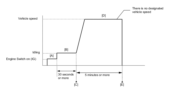
CONFIRMATION DRIVING PATTERN
-
Connect the GTS to the DLC3.
-
Turn the engine switch on (IG).
-
Turn the GTS on.
-
Clear the DTCs (even if no DTCs are stored, perform the clear DTC procedure).
-
Turn the engine switch off and wait for at least 30 seconds.
-
Turn the engine switch on (IG) [A].
-
Turn the GTS on.
-
Start the engine and idle it for 30 seconds or more [B].
-
Enter the following menus: Powertrain / Engine / Trouble Codes [C].
-
Read the pending DTCs.
Tech Tips
-
If a pending DTC is output, the system is malfunctioning.
-
If a pending DTC is not output, perform the following procedure.
-
-
Enter the following menus: Powertrain / Engine / Utility / All Readiness.
-
Input the DTC: P136201 or P136301.
-
Check the DTC judgment result.
GTS Display Description NORMAL
-
DTC judgment completed
-
System normal
ABNORMAL
-
DTC judgment completed
-
System abnormal
INCOMPLETE
-
DTC judgment not completed
-
Perform driving pattern after confirming DTC enabling conditions
Tech Tips
-
If the judgment result is NORMAL, the system is normal.
-
If the judgment result is ABNORMAL, the system has a malfunction.
-
If the judgment result is INCOMPLETE, perform steps [D] through [E].
-
-
Drive the vehicle for 5 minutes or more [D].
CAUTION:
When performing the confirmation driving pattern, obey all speed limits and traffic laws.
-
Enter the following menus: Powertrain / Engine / Trouble Codes [E].
-
Read the pending DTCs.
Tech Tips
-
If a pending DTC is output, the system is malfunctioning.
-
If a pending DTC is not output, perform the following procedure.
-
-
Enter the following menus: Powertrain / Engine / Utility / All Readiness.
-
Input the DTC: P136201 or P136301.
-
Check the DTC judgment result.
Tech Tips
-
If the judgment result is NORMAL, the system is normal.
-
If the judgment result is ABNORMAL, the system has a malfunction.
-
CAUTION / NOTICE / HINT
Note
Inspect the fuses for circuits related to this system before performing the following procedure.
Tech Tips
-
Read Freeze Frame Data using the GTS. The ECM records vehicle and driving condition information as Freeze Frame Data the moment a DTC is stored. When troubleshooting, Freeze Frame Data can help determine if the vehicle was moving or stationary, if the engine was warmed up or not, if the air fuel ratio was lean or rich, and other data from the time the malfunction occurred.
-
Bank 1 refers to the bank that includes the No. 1 cylinder*.
*: The No. 1 cylinder is the cylinder which is farthest from the transmission.
-
Bank 2 refers to the bank that does not include the No. 1 cylinder.
DTC Suspected Area P136201 Bank 1 P136301 Bank 2
PROCEDURE
-
CHECK TERMINAL VOLTAGE (POWER SOURCE OF CAM TIMING CONTROL MOTOR WITH EDU ASSEMBLY)
-
Disconnect the cam timing control motor with EDU assembly connector.
-
Turn the engine switch on (IG).
-
Measure the voltage according to the value(s) in the table below.
Standard Voltage Tester Connection Condition Specified Condition D53-2 (VB1) - Body ground Engine switch on (IG) 11 to 14 V D54-2 (VB1) - Body ground Engine switch on (IG) 11 to 14 V Result Proceed to OK NG
NG 
INSPECT VVT NO. 1 RELAY OR VVT NO. 2 RELAY Click here
OK 
-
-
CHECK HARNESS AND CONNECTOR (CAM TIMING CONTROL MOTOR WITH EDU ASSEMBLY - BODY GROUND)
-
Disconnect the cam timing control motor with EDU assembly connector.
-
Measure the resistance according to the value(s) in the table below.
Standard Resistance Tester Connection Condition Specified Condition D53-3 (GND) - Body ground Always Below 1 Ω D54-3 (GND) - Body ground Always Below 1 Ω Result Proceed to OK NG
NG 
REPAIR OR REPLACE HARNESS OR CONNECTOR
OK
-
-
INSPECT CAM TIMING CONTROL MOTOR WITH EDU ASSEMBLY (BODY GROUND)
-
Check installation condition.
-
Check that the 3 installation bolts of the cam timing control motor with EDU assembly are tightened to the specified torque.
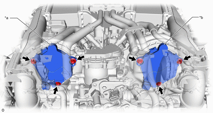
*a Cam Timing Control Motor with EDU Assembly (Bank 1) *b Cam Timing Control Motor with EDU Assembly (Bank 2) Torque 21 N*m (214 kgf*cm, 15 ft.*lbf) Result Proceed to OK NG -
NG
TIGHTEN TO SPECIFIED TORQUE
OK
-
-
CHECK HARNESS AND CONNECTOR (CAM TIMING CONTROL MOTOR WITH EDU ASSEMBLY - ECM)
-
Disconnect the cam timing control motor with EDU assembly connector.
-
Disconnect the ECM connector.
-
Measure the resistance according to the value(s) in the table below.
Standard Resistance Tester Connection Condition Specified Condition D53-5 (VTD1) - D1-54 (EMF1) Always Below 1 Ω D54-5 (VTD1) - D1-44 (EMF2) Always Below 1 Ω D53-5 (VTD1) or D1-54 (EMF1) - Body ground and other terminals Always 10 kΩ or higher D54-5 (VTD1) or D1-44 (EMF2) - Body ground and other terminals Always 10 kΩ or higher Result Proceed to OK NG
NG
REPAIR OR REPLACE HARNESS OR CONNECTOR
OK
-
-
REPLACE CAM TIMING CONTROL MOTOR WITH EDU ASSEMBLY
-
Replace the cam timing control motor with EDU assembly.
for bank 1: Click here
for bank 2: Click here
Tech Tips
Perform "Inspection After Repair" after replacing the cam timing control motor with EDU assembly.
Result Proceed to NEXT
NEXT
-
-
CLEAR DTC
-
Connect the GTS to the DLC3.
-
Turn the engine switch on (IG).
-
Turn the GTS on.
-
Clear the DTCs.
Powertrain > Engine > Clear DTCs -
Turn the engine switch off and wait for at least 30 seconds.
Result Proceed to NEXT
NEXT
-
-
CONFIRM WHETHER MALFUNCTION HAS BEEN SUCCESSFULLY REPAIRED
-
Drive the vehicle in accordance with the driving pattern described in Confirmation Driving Pattern.
-
Enter the following menus: Powertrain / Engine / Trouble Codes.
-
Read the DTCs.
Powertrain > Engine > Trouble CodesResult Result Proceed to DTCs are not output A DTC P136201 or P136301 is output B
A
END
B
REPLACE ECM Click here
-
-
INSPECT VVT NO. 1 RELAY OR VVT NO. 2 RELAY
-
Inspect the VVT NO. 1 relay or VVT NO. 2 relay.
Result Proceed to OK NG
NG
REPLACE VVT NO. 1 RELAY OR VVT NO. 2 RELAY
OK
-
-
CHECK HARNESS AND CONNECTOR (POWER SOURCE OF VVT NO. 1 RELAY OR VVT NO. 2 RELAY)
-
Remove the VVT NO. 1 relay or VVT NO. 2 relay from the No. 1 engine room relay block and junction block assembly.
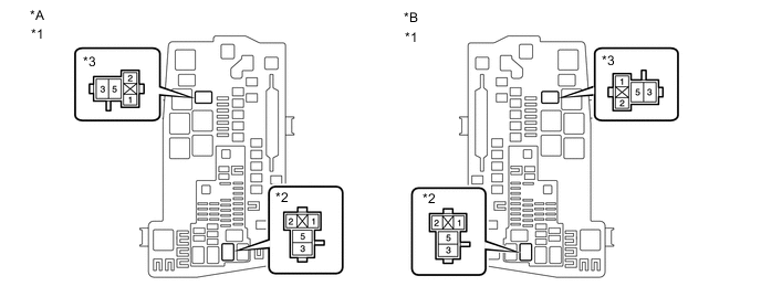
*A for LHD *B for RHD *1 No. 1 Engine Room Relay Block and Junction Block Assembly *2 VVT NO. 1 Relay *3 VVT NO. 2 Relay - - -
Measure the voltage according to the value(s) in the table below.
Standard Voltage Tester Connection Condition Specified Condition 3 (VVT NO. 1 relay) - Body ground Always 11 to 14 V 3 (VVT NO. 2 relay) - Body ground Always 11 to 14 V Result Proceed to OK NG
NG
REPAIR OR REPLACE HARNESS OR CONNECTOR (BATTERY - VVT NO. 1 RELAY OR VVT NO. 2 RELAY)
OK
-
-
CHECK HARNESS AND CONNECTOR (VVT NO. 1 RELAY OR VVT NO. 2 RELAY - BODY GROUND)
-
Remove the VVT NO. 1 relay or VVT NO. 2 relay from the No. 1 engine room relay block and junction block assembly.
-
Measure the resistance according to the value(s) in the table below.
Standard Resistance Tester Connection Condition Specified Condition 2 (VVT NO. 1 relay) - Body ground Always Below 1 Ω 2 (VVT NO. 2 relay) - Body ground Always Below 1 Ω Result Proceed to OK NG
NG
REPAIR OR REPLACE HARNESS OR CONNECTOR
OK
-
-
CHECK HARNESS AND CONNECTOR (VVT NO. 1 RELAY OR VVT NO. 2 RELAY - CAM TIMING CONTROL MOTOR WITH EDU ASSEMBLY)
-
Remove the VVT NO. 1 relay or VVT NO. 2 relay from the No. 1 engine room relay block and junction block assembly.
-
Disconnect the cam timing control motor with EDU assembly connector.
-
Measure the resistance according to the value(s) in the table below.
Standard Resistance Tester Connection Condition Specified Condition 5 (VVT NO. 1 relay) - D53-2 (VB1) Always Below 1 Ω 5 (VVT NO. 2 relay) - D54-2 (VB1) Always Below 1 Ω 5 (VVT NO. 1 relay) or D53-2 (VB1) - Body ground and other terminals Always 10 kΩ or higher 5 (VVT NO. 2 relay) or D54-2 (VB1) - Body ground and other terminals Always 10 kΩ or higher Result Proceed to OK NG
NG
REPAIR OR REPLACE HARNESS OR CONNECTOR
OK
-
-
CHECK HARNESS AND CONNECTOR (EFI-MAIN NO. 3 RELAY - VVT NO. 1 RELAY OR VVT NO. 2 RELAY)
-
Remove the EFI-MAIN NO. 3 relay, A/F HTR relay, VVT NO. 1 relay and VVT NO. 2 relay from the No. 1 engine room relay block and junction block assembly.
Tech Tips
Remove the A/F HTR relay connected between the checked terminals as the coil inside the relay influences the measurement value.
-
Measure the resistance according to the value(s) in the table below.
Standard Resistance Tester Connection Condition Specified Condition 5 (EFI-MAIN NO. 3 relay) - 1 (VVT NO. 1 relay) Always Below 1 Ω 5 (EFI-MAIN NO. 3 relay) - 1 (VVT NO. 2 relay) Always Below 1 Ω 5 (EFI-MAIN NO. 3 relay) or 1 (VVT NO. 1 relay) - Body ground and other terminals Always 10 kΩ or higher 5 (EFI-MAIN NO. 3 relay) or 1 (VVT NO. 2 relay) - Body ground and other terminals Always 10 kΩ or higher Result Proceed to OK NG
NG
REPAIR OR REPLACE HARNESS OR CONNECTOR
OK
-
-
INSPECT EFI-MAIN NO. 3 RELAY
-
Inspect the EFI-MAIN NO. 3 relay.
Result Proceed to OK NG
NG
REPLACE EFI-MAIN NO. 3 RELAY
OK
-
-
CHECK TERMINAL VOLTAGE (POWER SOURCE OF EFI-MAIN NO. 3 RELAY)
-
Remove the EFI-MAIN NO. 3 relay from the No. 1 engine room relay block and junction block assembly.
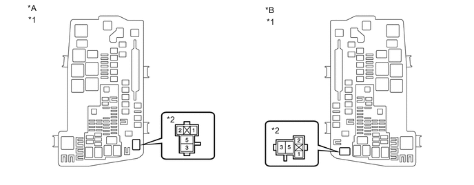
*A for LHD *B for RHD *1 No. 1 Engine Room Relay Block and Junction Block Assembly *2 EFI-MAIN NO. 3 Relay -
Measure the voltage according to the value(s) in the table below.
Standard Voltage Tester Connection Condition Specified Condition 3 (EFI-MAIN NO. 3 relay) - Body ground Always 11 to 14 V Result Proceed to OK NG
NG
REPAIR OR REPLACE HARNESS OR CONNECTOR
OK
-
-
CHECK HARNESS AND CONNECTOR (EFI-MAIN NO. 3 RELAY - BODY GROUND)
-
Remove the EFI-MAIN NO. 3 relay from the No. 1 engine room relay block and junction block assembly.
-
Measure the resistance according to the value(s) in the table below.
Standard Resistance Tester Connection Condition Specified Condition 1 (EFI-MAIN NO. 3 relay) - Body ground Always Below 1 Ω Result Proceed to OK NG
OK
REPAIR OR REPLACE HARNESS OR CONNECTOR (EFI-MAIN NO. 1 RELAY - EFI-MAIN NO. 3 RELAY)
NG
REPAIR OR REPLACE HARNESS OR CONNECTOR
-