COMPRESSOR(for 1UR-FE) INSTALLATION
PROCEDURE
ADJUST COMPRESSOR OIL
When replacing the cooler compressor with a new one, gradually discharge the refrigerant gas from the service valve, and then drain the following amount of oil from the new cooler compressor before installation.
Standard
(Oil capacity inside the new cooler compressor: 135 + 15 cc (4.57 + 0.51 fl.oz.)) - (Remaining oil amount in the removed compressor and magnetic clutch) = (Oil amount to be removed from the new compressor when replacing)
Note:When checking the compressor oil level, follow the A/C system precautions.
If a new cooler compressor is installed without removing some oil remaining in the pipes of the vehicle, the oil amount will be too large. This prevents heat exchange in the refrigerant cycle and causes refrigerant failure.
If the volume of oil remaining in the removed cooler compressor is too small, check for oil leakage.
Be sure to use ND-OIL 8 or equivalent for compressor oil.
INSTALL COOLER COMPRESSOR ASSEMBLY
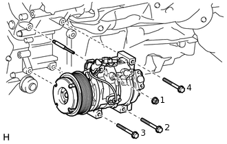
Install the stud bolt.
10 N*m
102 kgf*cm
7 ft.*lbf
Temporarily install the cooler compressor assembly with the 3 bolts and nut.
Tighten the 3 bolts and nut in the sequence shown in the illustration.
for bolt
25 N*m
255 kgf*cm
18 ft.*lbf
for nut
25 N*m
255 kgf*cm
18 ft.*lbf
Connect the connector.
CONNECT SUCTION HOSE SUB-ASSEMBLY
Remove the attached vinyl tape from the hose.
Sufficiently apply compressor oil to a new O-ring and the fitting surface of the cooler compressor.
Compressor oil
ND-OIL 8 or equivalent
Install the O-ring to the suction hose.
-
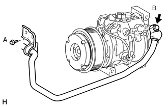
Connect the suction hose to the cooler compressor with the 2 bolts.
for bolt A
7.8 N*m
80 kgf*cm
69 in.*lbf
for bolt B
9.8 N*m
100 kgf*cm
87 in.*lbf
CONNECT DISCHARGE HOSE SUB-ASSEMBLY
Remove the attached vinyl tape from the hose.
Sufficiently apply compressor oil to a new O-ring and the fitting surface of the cooler compressor.
Compressor oil
ND-OIL 8 or equivalent
Install the O-ring to the discharge hose.
-
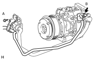
Connect the discharge hose to the cooler compressor with the bolt.
for bolt A
7.8 N*m
80 kgf*cm
69 in.*lbf
for bolt B
9.8 N*m
100 kgf*cm
87 in.*lbf
INSTALL FAN SHROUD
INSTALL NO. 1 RADIATOR HOSE
INSTALL RADIATOR RESERVOIR ASSEMBLY
INSTALL FRONT FENDER APRON SEAL LH
INSTALL REAR ENGINE UNDER COVER ASSEMBLY
INSTALL TRANSMISSION UNDER COVER
INSTALL NO. 1 ENGINE UNDER COVER SUB-ASSEMBLY
INSTALL LOWER FRONT BUMPER COVER
ADD ENGINE COOLANT
INSTALL FAN AND GENERATOR V BELT
Install the fan and generator V belt (Click here).
CHECK FOR COOLANT LEAK
CHARGE REFRIGERANT
WARM UP ENGINE
CHECK FOR REFRIGERANT GAS LEAK