SHIFT AND SELECT ACTUATOR INSTALLATION
PROCEDURE
INSTALL SHIFT AND SELECT ACTUATOR ASSEMBLY
Clean the contact surfaces of the shift and select actuator assembly and manual transmission case with a non-residue solvent.
-
*a
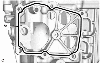
FIPG
Seal Diameter 1.2 mm (0.0472 in.)
Apply FIPG in a continuous line to the shift and select actuator assembly as shown in the illustration.
FIPG
Toyota Genuine Seal Packing 1281, Three Bond 1281 or equivalent.
Note:Remove any oil from the contact surfaces.
Install the parts within 10 minutes of application. Otherwise, the seal packing (FIPG) must be removed and reapplied.
-
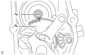
*a
Ring Gear
*b
Lever To Rotate Shift And Select Lever Shaft
Make sure that the 8th tooth from the left of the lever to rotate the shift and select lever shaft is meshed with the tooth groove of the ring gear as shown in the illustration.
-
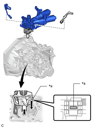
*a
Inner No. 1 Shift Lever
Install the shift and select actuator assembly and 2 wire harness clamp brackets to the manual transmission case with the 6 bolts.
18 N*m
184 kgf*cm
13 ft.*lbf
Note:Make sure that the shift fork shaft lever is in the neutral position when installing the shift and select actuator assembly, otherwise the shift and select actuator assembly, No. 1 gear shift head, No. 2 gear shift fork shaft or No. 3 gear shift head may be deformed.
Install the wire harness clamp bracket to the shift and select actuator assembly with the bolt.
12.8 N*m
131 kgf*cm
9 ft.*lbf
INSTALL NO. 1 LOCK BALL ASSEMBLY
Clean and degrease the No. 1 lock ball assembly and installation hole in the manual transmission case.
-
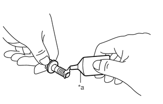
*a
Adhesive
Apply adhesive to the No. 1 lock ball assembly threads.
Adhesive
Toyota Genuine Adhesive 1324, Three Bond 1324 or equivalent
Note:In order to ensure proper installation of the No. 1 lock ball assembly, apply adhesive to the No. 1 lock ball assembly and install it within 10 minutes of adhesive application.
-
Using a 18 mm socket wrench, install the No. 1 lock ball assembly to the manual transmission case.
36.8 N*m
375 kgf*cm
27 ft.*lbf
Note:Do not install the No. 1 lock ball assembly with a gasket. Apply adhesive to the No. 1 lock ball assembly and install it.
If the No. 1 lock ball assembly is installed with a gasket, the transaxle may jump out of gear.
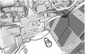
INSTALL PARK/NEUTRAL POSITION SWITCH ASSEMBLY
-
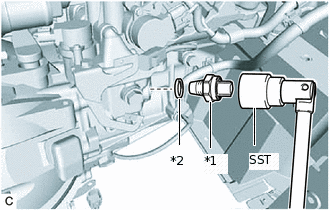
*1
Park/Neutral Position Switch Assembly
*2
Gasket
Using SST, install the park/neutral position switch assembly and a new gasket to the multi-mode manual transaxle assembly.
09817-16011
39.2 N*m
400 kgf*cm
29 ft.*lbf
-

Connect the park/neutral position switch assembly connector.
-
CONNECT WIRE HARNESS
Connect the transmission revolution sensor connector.
Connect the back-up light switch assembly connector.
Connect the shift stroke sensor connector.
Connect the park/neutral position switch assembly connector.
Engage the 4 wire harness clamps.
Connect the select stroke sensor connector.
Connect the 2 shift and select actuator assembly connectors.
Install the wire harness clamp bracket to the shift and select actuator assembly with the bolt.
12.8 N*m
131 kgf*cm
9 ft.*lbf
Engage the 2 wire harness clamps.
INSTALL CLUTCH ACTUATOR ASSEMBLY
PERFORM INITIALIZATION AND LEARNING
PERFORM SYNCHRONIZATION POSITION CALIBRATION