CAN COMMUNICATION SYSTEM(w/o Central Gateway ECU) Check CAN Bus Lines for Short Circuit (LHD Models)
| DTC Code | DTC Name |
|---|---|
| Check CAN Bus Lines for Short Circuit (LHD Models) |
DESCRIPTION
There may be a short circuit between the V bus main lines and/or CAN branch lines when the resistance between terminals 6 (CANH) and 14 (CANL) of the DLC3 is below 54 Ω.
Symptom |
Trouble Area |
|---|---|
Resistance between terminals 6 (CANH) and 14 (CANL) of DLC3 is below 54 Ω. |
|
*1: w/ Entry and Start System
*2: w/ VSC
*3: for Radio and Display Type
*4: w/ Air Conditioning System
*5: w/ Simple Intelligent Parking Assist System
*6: w/ Stop and Start System
*7: w/ AFS (Adaptive Front-lighting System)
*8: for 1ND-TV Engine with Cruise Control System
WIRING DIAGRAM
CAUTION / NOTICE / HINT
Before measuring the resistance of the CAN bus, turn the ignition switch off and leave the vehicle for 1 minute or more without operating the key or any switches, or opening or closing the doors. After that, disconnect the cable from the negative (-) battery terminal and leave the vehicle for 1 minute or more before measuring the resistance.
After turning the ignition switch off, waiting time may be required before disconnecting the cable from the negative (-) battery terminal. Therefore, make sure to read the disconnecting the cable from the negative (-) battery terminal notices before proceeding with work.
Because the order of diagnosis is important to allow correct diagnosis, make sure to begin troubleshooting using How to Proceed with Troubleshooting when CAN communication system related DTCs are output.
After performing repairs, perform the DTC check procedure and confirm that the DTCs are not output again.
DTC check procedure: Turn the ignition switch to ON and wait at least 31 seconds, and then drive the vehicle at a speed of 20 km/h (12 mph) or more.
After the repair, perform the CAN bus check and check that all the ECUs and sensors connected to the CAN communication system are displayed.
Operating the ignition switch, any other switches or a door triggers related ECU and sensor communication on the CAN. This communication will cause the resistance value to change.
Even after DTCs are cleared, if a DTC is stored again after driving the vehicle for a while, the malfunction may be occurring due to vibration of the vehicle. In such a case, wiggling the ECUs or wire harness while performing the inspection below may help determine the cause of the malfunction.
PROCEDURE
CHECK FOR SHORT IN CAN BUS LINES (COMBINATION METER ASSEMBLY - NO. 3 CAN JUNCTION CONNECTOR)
Disconnect the cable from the negative (-) battery terminal.
-
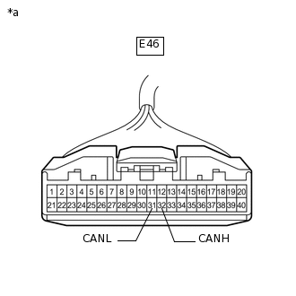
*a
Front view of wire harness connector
(to Combination Meter Assembly)
Disconnect the E46 combination meter assembly connector.
Measure the resistance according to the value(s) in the table below.
Standard Resistance
Tester Connection
Condition
Specified Condition
E46-32 (CANH) - E46-31 (CANL)
Cable disconnected from negative (-) battery terminal
108 to 132 Ω
Result
Result
Proceed to
OK
A
NG (for 1NR-FE, 1ZR-FAE, 1ZR-FE or 2ZR-FE engine)
B
NG (for 1ND-TV engine)
C
NG (for 1AD-FTV engine)
D
C CHECK FOR SHORT IN CAN BUS LINES (ECM - NO. 1 CAN JUNCTION CONNECTOR)Click here
D CHECK FOR SHORT IN CAN BUS LINES (ECM - NO. 1 CAN JUNCTION CONNECTOR)Click here
CHECK FOR SHORT IN CAN BUS LINES (ECM - NO. 1 CAN JUNCTION CONNECTOR)
Reconnect the E46 combination meter assembly connector.
-
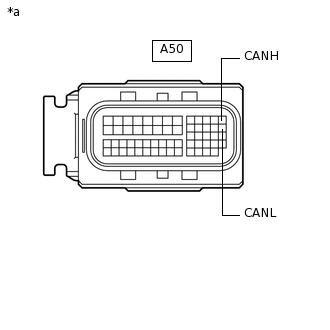
*a
Front view of wire harness connector
(to ECM)
Disconnect the A50 ECM connector.
Measure the resistance according to the value(s) in the table below.
Standard Resistance
Tester Connection
Condition
Specified Condition
A50-13 (CANH) - A50-26 (CANL)
Cable disconnected from negative (-) battery terminal
108 to 132 Ω
Result
Result
Proceed to
OK (for 1NR-FE engine)
A
OK (for 1ZR-FAE engine)
B
OK (for 1ZR-FE engine)
C
OK (for 2ZR-FE engine)
D
NG
E
E CHECK FOR SHORT IN CAN BUS LINES (NO. 3 CAN JUNCTION CONNECTOR)Click here
CHECK FOR SHORT IN CAN BUS LINES (ECM - NO. 1 CAN JUNCTION CONNECTOR)
Reconnect the E46 combination meter assembly connector.
-
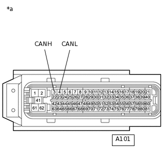
*a
Front view of wire harness connector
(to ECM)
Disconnect the A101 ECM connector.
Measure the resistance according to the value(s) in the table below.
Standard Resistance
Tester Connection
Condition
Specified Condition
A101-3 (CANH) - A101-4 (CANL)
Cable disconnected from negative (-) battery terminal
108 to 132 Ω
Result
Result
Proceed to
OK
A
NG (for Hatchback, Wagon)
B
NG (for Sedan)
C
C CHECK FOR SHORT IN CAN BUS LINES (NO. 3 CAN JUNCTION CONNECTOR)Click here
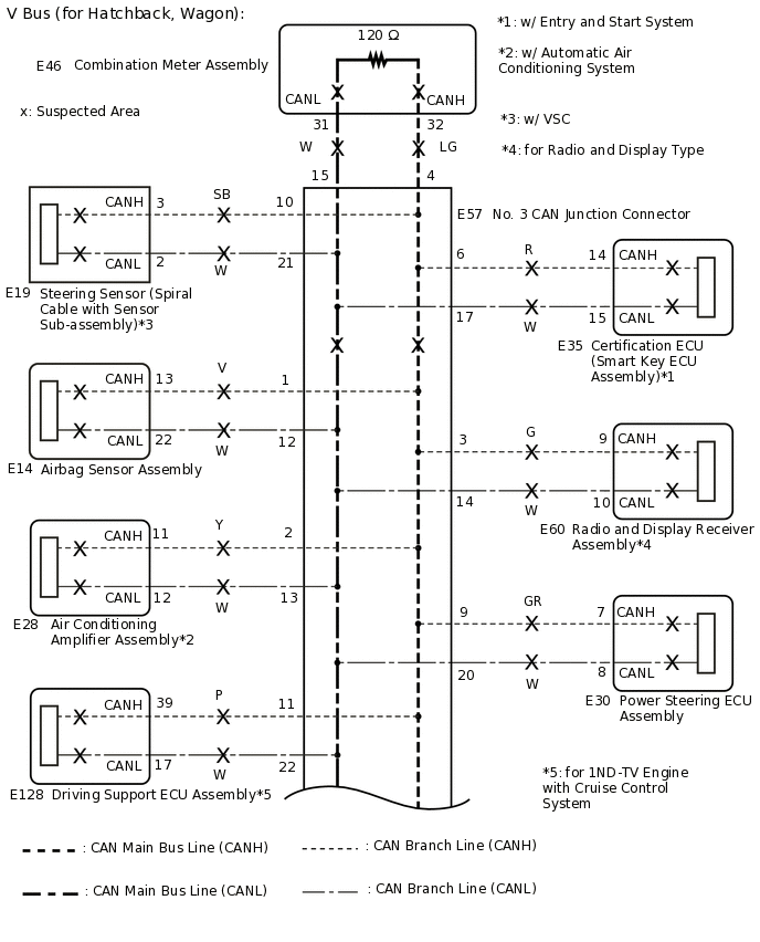
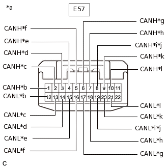
CHECK FOR SHORT IN CAN BUS LINES (NO. 3 CAN JUNCTION CONNECTOR)
Reconnect the A101 ECM connector.
-
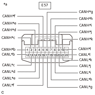
*a
Front view of wire harness connector
(to No. 3 CAN Junction Connector)
*b
to Airbag Sensor Assembly
*c
to Air Conditioning Amplifier Assembly*1
*d
to Radio and Display Receiver Assembly*2
*e
to Combination Meter Assembly
*f
to No. 1 CAN Junction Connector
*g
to Certification ECU (Smart Key ECU Assembly)*3
*h
to Clearance Warning ECU Assembly*4
*i
to Engine Stop and Start ECU*5
*j
to Power Steering ECU Assembly
*k
to Steering Sensor (Spiral Cable with Sensor Sub-assembly)*6
*l
to Driving Support ECU Assembly*7
Disconnect the E57 No. 3 CAN junction connector.
*1: w/ Automatic Air Conditioning System
*2: for Radio and Display Type
*3: w/ Entry and Start System
*4: w/ Simple Intelligent Parking Assist System
*5: w/ Stop and Start System
*6: w/ VSC
*7: w/ Cruise Control System
Measure the resistance according to the value(s) in the table below.
Standard Resistance
Tester Connection
Condition
Specified Condition
Connected to
E57-1 (CANH) - E57-12 (CANL)
Cable disconnected from negative (-) battery terminal
200 Ω or higher
Airbag sensor assembly
E57-2 (CANH) - E57-13 (CANL)
Cable disconnected from negative (-) battery terminal
200 Ω or higher
Air conditioning amplifier assembly*1
E57-3 (CANH) - E57-14 (CANL)
Cable disconnected from negative (-) battery terminal
200 Ω or higher
Radio and display receiver assembly*2
E57-4 (CANH) - E57-15 (CANL)
Cable disconnected from negative (-) battery terminal
108 to 132 Ω
Combination meter assembly
E57-5 (CANH) - E57-16 (CANL)
Cable disconnected from negative (-) battery terminal
108 to 132 Ω
No. 1 CAN junction connector
E57-6 (CANH) - E57-17 (CANL)
Cable disconnected from negative (-) battery terminal
200 Ω or higher
Certification ECU (smart key ECU assembly)*3
E57-7 (CANH) - E57-18 (CANL)
Cable disconnected from negative (-) battery terminal
200 Ω or higher
Clearance warning ECU assembly*4
E57-8 (CANH) - E57-19 (CANL)
Cable disconnected from negative (-) battery terminal
200 Ω or higher
Engine stop and start ECU*5
E57-9 (CANH) - E57-20 (CANL)
Cable disconnected from negative (-) battery terminal
200 Ω or higher
Power steering ECU assembly
E57-10 (CANH) - E57-21 (CANL)
Cable disconnected from negative (-) battery terminal
200 Ω or higher
Steering sensor (spiral cable with sensor sub-assembly)*6
E57-11 (CANH) - E57-22 (CANL)
Cable disconnected from negative (-) battery terminal
200 Ω or higher
Driving support ECU assembly*7
*1: w/ Automatic Air Conditioning System
*2: for Radio and Display Type
*3: w/ Entry and Start System
*4: w/ Simple Intelligent Parking Assist System
*5: w/ Stop and Start System
*6: w/ VSC
*7: w/ Cruise Control System
Result
Result
Proceed to
OK
A
NG (No. 1 CAN junction connector main line)
B
NG (ECU or sensor branch line)
C
NG (Combination meter assembly main line)
D
A REPLACE NO. 3 CAN JUNCTION CONNECTOR
B CHECK FOR SHORT IN CAN BUS LINES (NO. 1 CAN JUNCTION CONNECTOR)Click here
C CHECK FOR SHORT IN CAN BUS LINES (ECU, SENSOR)Click here
D REPAIR OR REPLACE CAN MAIN BUS LINE OR CONNECTOR (COMBINATION METER ASSEMBLY - NO. 3 CAN JUNCTION CONNECTOR)
CHECK FOR SHORT IN CAN BUS LINES (NO. 3 CAN JUNCTION CONNECTOR)
Reconnect the A101 ECM connector.
-
*a
Front view of wire harness connector
(to No. 3 CAN Junction Connector)
*b
to Airbag Sensor Assembly
*c
to Air Conditioning Amplifier Assembly*1
*d
to Radio and Display Receiver Assembly*2
*e
to Combination Meter Assembly
*f
to No. 1 CAN Junction Connector
*g
to Certification ECU (Smart Key ECU Assembly)*3
*h
to Clearance Warning ECU Assembly*4
*i
to Engine Stop and Start ECU*5
*j
to Driving Support ECU Assembly*6
*k
to Power Steering ECU Assembly
*l
to Steering Sensor (Spiral Cable with Sensor Sub-assembly)*7
Disconnect the E57 No. 3 CAN junction connector.
*1: w/ Air Conditioning System
*2: for Radio and Display Type
*3: w/ Entry and Start System
*4: w/ Simple Intelligent Parking Assist System
*5: w/ Stop and Start System
*6: w/ Cruise Control System
*7: w/ VSC
Measure the resistance according to the value(s) in the table below.
Standard Resistance
Tester Connection
Condition
Specified Condition
Connected to
E57-1 (CANH) - E57-12 (CANL)
Cable disconnected from negative (-) battery terminal
200 Ω or higher
Airbag sensor assembly
E57-2 (CANH) - E57-13 (CANL)
Cable disconnected from negative (-) battery terminal
200 Ω or higher
Air conditioning amplifier assembly*1
E57-3 (CANH) - E57-14 (CANL)
Cable disconnected from negative (-) battery terminal
200 Ω or higher
Radio and display receiver assembly*2
E57-4 (CANH) - E57-15 (CANL)
Cable disconnected from negative (-) battery terminal
108 to 132 Ω
Combination meter assembly
E57-5 (CANH) - E57-16 (CANL)
Cable disconnected from negative (-) battery terminal
108 to 132 Ω
No. 1 CAN junction connector
E57-6 (CANH) - E57-17 (CANL)
Cable disconnected from negative (-) battery terminal
200 Ω or higher
Certification ECU (smart key ECU assembly)*3
E57-7 (CANH) - E57-18 (CANL)
Cable disconnected from negative (-) battery terminal
200 Ω or higher
Clearance warning ECU assembly*4
E57-8 (CANH) - E57-19 (CANL)
Cable disconnected from negative (-) battery terminal
200 Ω or higher
Engine stop and start ECU*5
E57-8 (CANH) - E57-19 (CANL)
Cable disconnected from negative (-) battery terminal
200 Ω or higher
Driving support ECU assembly*6
E57-9 (CANH) - E57-20 (CANL)
Cable disconnected from negative (-) battery terminal
200 Ω or higher
Power steering ECU assembly
E57-10 (CANH) - E57-21 (CANL)
Cable disconnected from negative (-) battery terminal
200 Ω or higher
Steering sensor (spiral cable with sensor sub-assembly)*7
*1: w/ Air Conditioning System
*2: for Radio and Display Type
*3: w/ Entry and Start System
*4: w/ Simple Intelligent Parking Assist System
*5: w/ Stop and Start System
*6: w/ Cruise Control System
*7: w/ VSC
Result
Result
Proceed to
OK
A
NG (No. 1 CAN junction connector main line)
B
NG (ECU or sensor branch line)
C
NG (Combination meter assembly main line)
D
A REPLACE NO. 3 CAN JUNCTION CONNECTOR
C CHECK FOR SHORT IN CAN BUS LINES (ECU, SENSOR)Click here
D REPAIR OR REPLACE CAN MAIN BUS LINE OR CONNECTOR (COMBINATION METER ASSEMBLY - NO. 3 CAN JUNCTION CONNECTOR)
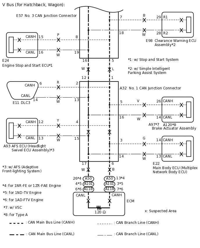
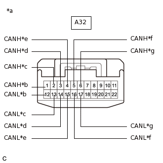
CHECK FOR SHORT IN CAN BUS LINES (NO. 1 CAN JUNCTION CONNECTOR)
-
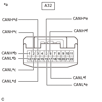
*a
Front view of wire harness connector
(to No. 1 CAN Junction Connector)
*b
to No. 3 CAN Junction Connector
*c
to DLC3
*d
to Main Body ECU (Multiplex Network Body ECU)
*e
to Brake Actuator Assembly
*f
to ECM
Disconnect the A32 No. 1 CAN junction connector.
Measure the resistance according to the value(s) in the table below.
Standard Resistance
Tester Connection
Condition
Specified Condition
Connected to
A32-1 (CANH) - A32-12 (CANL)
Cable disconnected from negative (-) battery terminal
1 MΩ or higher
No. 3 CAN junction connector
A32-2 (CANH) - A32-13 (CANL)
Cable disconnected from negative (-) battery terminal
1 MΩ or higher
DLC3
A32-3 (CANH) - A32-14 (CANL)
Cable disconnected from negative (-) battery terminal
200 Ω or higher
Main body ECU (multiplex network body ECU)
A32-5 (CANH) - A32-16 (CANL)
Cable disconnected from negative (-) battery terminal
200 Ω or higher
Brake actuator assembly
A32-6 (CANH) - A32-17 (CANL)
Cable disconnected from negative (-) battery terminal
108 to 132 Ω
ECM
Result
Result
Proceed to
OK
A
NG (No. 3 CAN junction connector main line)
B
NG (ECU or sensor branch line)
C
NG (DLC3 branch line)
D
NG (ECM main line)
E
A REPLACE NO. 1 CAN JUNCTION CONNECTOR
B REPAIR OR REPLACE CAN MAIN BUS LINE OR CONNECTOR (NO. 1 CAN JUNCTION CONNECTOR - NO. 3 CAN JUNCTION CONNECTOR)
C CHECK FOR SHORT IN CAN BUS LINES (ECU, SENSOR)Click here
D REPAIR OR REPLACE CAN BRANCH LINE CONNECTED TO DLC3
E REPAIR OR REPLACE CAN MAIN BUS LINE OR CONNECTOR (ECM - NO. 1 CAN JUNCTION CONNECTOR)
-
CHECK FOR SHORT IN CAN BUS LINES (ECM - NO. 1 CAN JUNCTION CONNECTOR)
Reconnect the E46 combination meter assembly connector.
-
*a
Front view of wire harness connector
(to ECM)
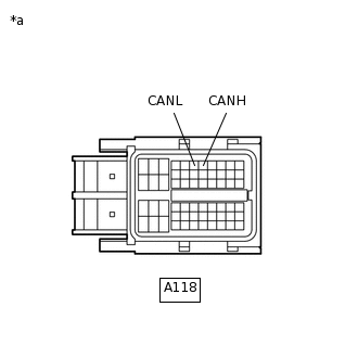
Disconnect the A118 ECM connector.
Measure the resistance according to the value(s) in the table below.
Standard Resistance
Tester Connection
Condition
Specified Condition
A118-7 (CANH) - A118-6 (CANL)
Cable disconnected from negative (-) battery terminal
108 to 132 Ω
Result
Result
OK
NG
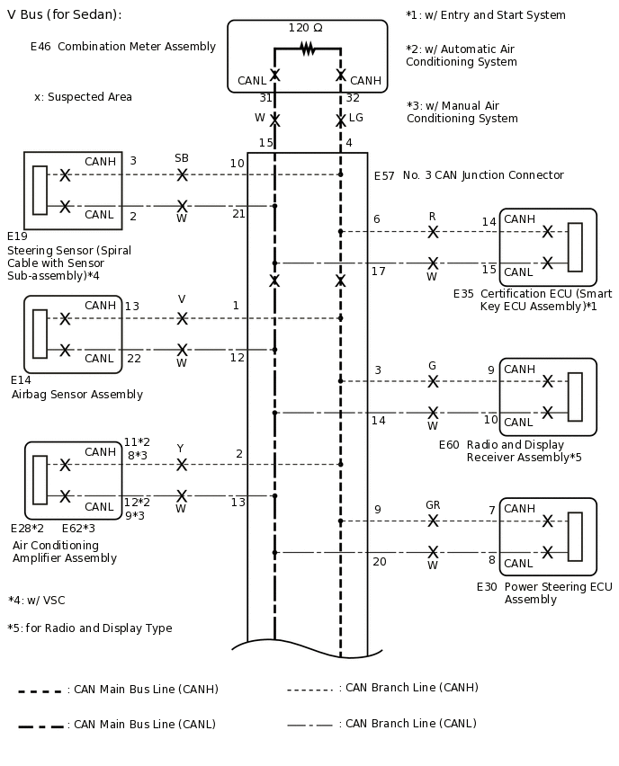
CHECK FOR SHORT IN CAN BUS LINES (NO. 3 CAN JUNCTION CONNECTOR)
Reconnect the A50 or A118 ECM connector.
-
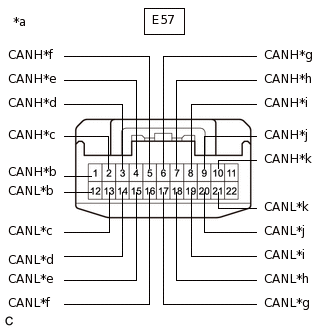
*a
Front view of wire harness connector
(to No. 3 CAN Junction Connector)
*b
to Airbag Sensor Assembly
*c
to Air Conditioning Amplifier Assembly*1
*d
to Radio and Display Receiver Assembly*2
*e
to Combination Meter Assembly
*f
to No. 1 CAN Junction Connector
*g
to Certification ECU (Smart Key ECU Assembly)*3
*h
to Clearance Warning ECU Assembly*4
*i
to Engine Stop and Start ECU*5
*j
to Power Steering ECU Assembly
*k
to Steering Sensor (Spiral Cable with Sensor Sub-assembly)*6
Disconnect the E57 No. 3 CAN junction connector.
*1: w/ Air Conditioning System
*2: for Radio and Display Type
*3: w/ Entry and Start System
*4: w/ Simple Intelligent Parking Assist System
*5: w/ Stop and Start System
*6: w/ VSC
Measure the resistance according to the value(s) in the table below.
Standard Resistance
Tester Connection
Condition
Specified Condition
Connected to
E57-1 (CANH) - E57-12 (CANL)
Cable disconnected from negative (-) battery terminal
200 Ω or higher
Airbag sensor assembly
E57-2 (CANH) - E57-13 (CANL)
Cable disconnected from negative (-) battery terminal
200 Ω or higher
Air conditioning amplifier assembly*1
E57-3 (CANH) - E57-14 (CANL)
Cable disconnected from negative (-) battery terminal
200 Ω or higher
Radio and display receiver assembly*2
E57-4 (CANH) - E57-15 (CANL)
Cable disconnected from negative (-) battery terminal
108 to 132 Ω
Combination meter assembly
E57-5 (CANH) - E57-16 (CANL)
Cable disconnected from negative (-) battery terminal
108 to 132 Ω
No. 1 CAN junction connector
E57-6 (CANH) - E57-17 (CANL)
Cable disconnected from negative (-) battery terminal
200 Ω or higher
Certification ECU (smart key ECU assembly)*3
E57-7 (CANH) - E57-18 (CANL)
Cable disconnected from negative (-) battery terminal
200 Ω or higher
Clearance warning ECU assembly*4
E57-8 (CANH) - E57-19 (CANL)
Cable disconnected from negative (-) battery terminal
200 Ω or higher
Engine stop and start ECU*5
E57-9 (CANH) - E57-20 (CANL)
Cable disconnected from negative (-) battery terminal
200 Ω or higher
Power steering ECU assembly
E57-10 (CANH) - E57-21 (CANL)
Cable disconnected from negative (-) battery terminal
200 Ω or higher
Steering sensor (spiral cable with sensor sub-assembly)*6
*1: w/ Air Conditioning System
*2: for Radio and Display Type
*3: w/ Entry and Start System
*4: w/ Simple Intelligent Parking Assist System
*5: w/ Stop and Start System
*6: w/ VSC
Result
Result
Proceed to
OK
A
NG (No. 1 CAN junction connector main line)
B
NG (ECU or sensor branch line)
C
NG (Combination meter assembly main line)
D
A REPLACE NO. 3 CAN JUNCTION CONNECTOR
C CHECK FOR SHORT IN CAN BUS LINES (ECU, SENSOR)Click here
D REPAIR OR REPLACE CAN MAIN BUS LINE OR CONNECTOR (COMBINATION METER ASSEMBLY - NO. 3 CAN JUNCTION CONNECTOR)
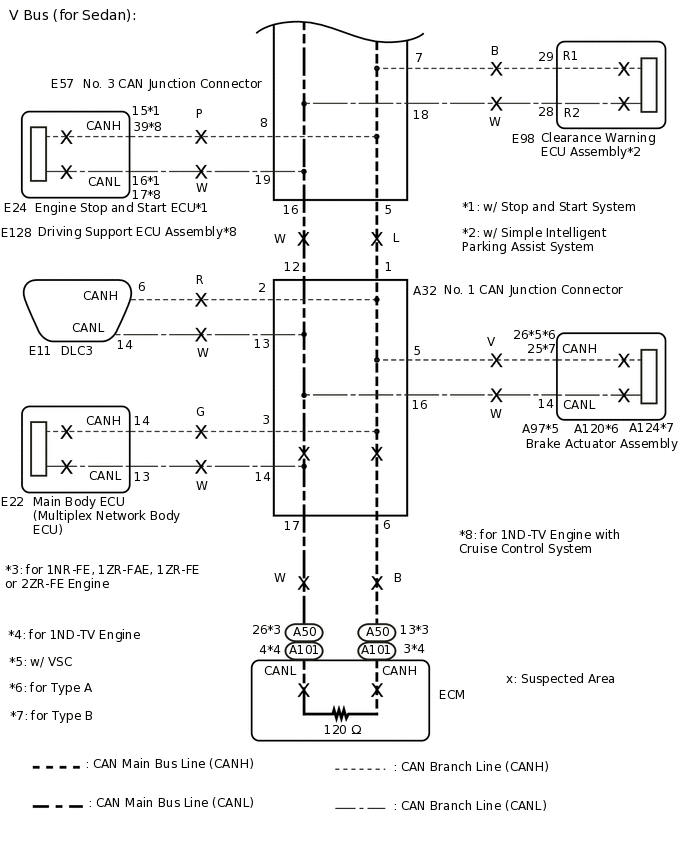
CHECK FOR SHORT IN CAN BUS LINES (NO. 1 CAN JUNCTION CONNECTOR)
-
*a
Front view of wire harness connector
(to No. 1 CAN Junction Connector)
*b
to No. 3 CAN Junction Connector
*c
to DLC3
*d
to Main Body ECU (Multiplex Network Body ECU)
*e
to AFS ECU (Headlight Swivel ECU Assembly)*
*f
to Brake Actuator Assembly
*g
to ECM
Disconnect the A32 No. 1 CAN junction connector.
*: w/ AFS (Adaptive Front-lighting System)
Measure the resistance according to the value(s) in the table below.
Standard Resistance
Tester Connection
Condition
Specified Condition
Connected to
A32-1 (CANH) - A32-12 (CANL)
Cable disconnected from negative (-) battery terminal
1 MΩ or higher
No. 3 CAN junction connector
A32-2 (CANH) - A32-13 (CANL)
Cable disconnected from negative (-) battery terminal
1 MΩ or higher
DLC3
A32-3 (CANH) - A32-14 (CANL)
Cable disconnected from negative (-) battery terminal
200 Ω or higher
Main body ECU (multiplex network body ECU)
A32-4 (CANH) - A32-15 (CANL)
Cable disconnected from negative (-) battery terminal
200 Ω or higher
AFS ECU (headlight swivel ECU assembly)*
A32-5 (CANH) - A32-16 (CANL)
Cable disconnected from negative (-) battery terminal
200 Ω or higher
Brake actuator assembly
A32-6 (CANH) - A32-17 (CANL)
Cable disconnected from negative (-) battery terminal
108 to 132 Ω
ECM
*: w/ AFS (Adaptive Front-lighting System)
Result
Result
Proceed to
OK
A
NG (No. 3 CAN junction connector main line)
B
NG (ECU or sensor branch line)
C
NG (DLC3 branch line)
D
NG (ECM main line)
E
A REPLACE NO. 1 CAN JUNCTION CONNECTOR
B REPAIR OR REPLACE CAN MAIN BUS LINE OR CONNECTOR (NO. 1 CAN JUNCTION CONNECTOR - NO. 3 CAN JUNCTION CONNECTOR)
D REPAIR OR REPLACE CAN BRANCH LINE CONNECTED TO DLC3
E REPAIR OR REPLACE CAN MAIN BUS LINE OR CONNECTOR (ECM - NO. 1 CAN JUNCTION CONNECTOR)
-
CHECK FOR SHORT IN CAN BUS LINES (ECU, SENSOR)
Reconnect all wire harness connectors (No. 1 CAN junction connector and No. 3 CAN junction connector).
Disconnect the connector that includes terminals CANH and CANL from the ECU or sensor to which the short circuited branch line is connected.
-
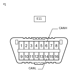
*1
DLC3
Measure the resistance according to the value(s) in the table below.
Standard Resistance
Tester Connection
Condition
Specified Condition
E11-6 (CANH) - E11-14 (CANL)
Cable disconnected from negative (-) battery terminal
54 to 69 Ω
Tip:If the resistance becomes normal (between 54 and 69 Ω) when the connector is disconnected from the ECU or sensor, there may be a short in the ECU or sensor.
Result
Result
OK
NG
OK REPLACE CORRESPONDING ECU OR SENSOR
NG REPAIR OR REPLACE CORRESPONDING ECU OR SENSOR BRANCH LINES OR CONNECTOR